


krohelm
-
Posts
83 -
Joined
-
Last visited
-
Days Won
2
krohelm's Achievements
")
Newbie (1/14)
4
Reputation
-
You might want to turn off accel enrich & spend a little more TLC time on your fuel? I went looking for a problem in your fuel table around ~85kpa at 2700-2800rpm, and you've got a canyon right exactly there that is 14% lower than the values of the cells on either side (11-12% absolute). Wildly configured accel enrich can throw your fuel table totally wonky (ask me how I know), it's best to get your fuel table right and then fix dynamics like dumping fuel when stabbing the throttle. Modelled fuel mode is great too... ;-)
-
I use DTM all over the place. It's worth the scratch to get a crimp tool in my opinion! This is the one I use for DTM's: https://prowireusa.com/p-1813-deutsch-dtm-mil-size-20-crimp-tool.aspx @Adamw: Totally, that's where I'm at but in my case 2 had the same problem despite providing clean separate power. I'm in love with the cap fix :-). If y'all want to try the dance again I've got my CAN-Lambda mounted in a convenient location & could return you this one for analysis. Not sure if we'd root cause it, but anyways feel free to reach out. I hope the cap fix works for you too @lysaer. Your thread sounds familiar
-
Sounds like your relay might be wired strangely. Can you rig it up right next to the ECU to test your intended wiring strategy? Usually I switch ground on my relays even if the ECU supports high side for special situations :-) Get out your multimeter and see if the relay is getting power across the coil, see if the relay is closing the circuit when powered, see if there is actually power that the relay is switching etc. Need more data!

-
Holy smokes, why am I only hearing of this now? I added a 22uf Nichicon (switching the power wires to nicer crimped Deutsch pins too) and just started the car, 0 waiting with key on. Within a few seconds, while it was running, the LSU 4.9 was operating normally. This has never happened before. These CAN-Lambda devices should come with the capacitor already on the plug, or better yet... in the potted enclosure. The stark difference in operation is nothing short of miraculous.

-
 krohelm reacted to a post in a topic:
CAN-Lambda Problem <Resolved>
krohelm reacted to a post in a topic:
CAN-Lambda Problem <Resolved>
-
Yeah, tough to see much without a log, but some of this looks really familiar to me. (everything looks like a nail, right?) 2 cents: You have Overrun Fuel Cut set to 1% TP. If your foot is light on the gas and the engine is warm you'll see "very lean." That part is "by design" and like an OEM system. If your TP sensor is good, you should consider using a TP lower than 1% for fuel cut. I have ITB's, but my TP sensor is well-configured. I use 0.1% throttle for overrun fuel cut. At 1% it surges and bucks really terribly while in slow traffic in my particular engine (TP ends up at around 0.2-0.4% in those situations for my engine. ymmv.) Accel Enrich was necessary for me to smooth out those spikes you see when you stab into the throttle. I was unable to achieve a repeatable tune without carefully configuring accel enrich. Get a low RPM cell (like 1000rpm) in good shape with steady state (find a hill and go up in 5th at 30mph WOT while logging haha) then do idle throttle stabs at 1000rpms while tuning out the lean spike with your accel enrich. This is what I did with my VE tune, but you're on Traditional fueling. Not sure how much different it may be to get your accel enrich roughed in. Good luck, and post logs! You'll get sorted. :-D
-
 krohelm changed their profile photo
 -
Hi @lysaer, I had a very brief time where it worked fine, then it went back to the same old problems. In the process of working with Link support, I was given a debug CAN configuration for the CAN-Lambda that causes it to power up the LSU 4.9 sensor while the engine is off. I have to use that configuration file and this is startup sequence: Key on. Wait 30-90 seconds while original post cycle spins. Observe lambda target indicator on dash flip from 0 to something above 0 (indicates o2 sensor has quit flapping and is active) Start engine. It never completes the heat cycle while the engine is on, with the possible exception of when it's already warm enough you might be able to get away with starting the engine while it isn't locked on. I have used original Toyota power/ground wires, fresh power/ground wires from the ECU 12v input (rests at 14.6 while running) about 36 inches long, and I have jumped the CAN-Lambda with 18 inch wires directly from the battery. In fact, I've powered the CAN-Lambda from a battery that is separate from the vehicle electrical system (18 inch leads) to isolate a problem with the car's power and the OP cycle continues regardless. I've attached the stream configuration my CAN-Lambda does not work without. I've tried 2 CAN-Lambdas and 4 or 5 LSU 4.9's, nothing has worked aside from this stream and the above startup process. The bright side is, it does work haha... I just got back from my first track day last weekend, and the instructor was vocally impressed with the way the engine ran. I never had a chance to tell him it had a Link in it :-). If I ever got this completely resolved I'd be incredibly happy - but I have no clue what else to try. Good luck! BTW, you should not use this configuration file. I use it, but I take 100% responsibility for using it in my own car. Just sharing it here for posterity & thread completeness. canlambda_test_stream.lcs
-
I just did a driving class at the local race track, and the (67 year old, seasoned) instructor was vocally excited about the way my car runs. I'm a hobbyist as well, and I selected the Monsoon a couple years ago. You can do really well as a novice with a Monsoon. 1. Monsoon does not have a built-in o2 sensor controller. You can install a controller and connect it to the Monsoon though! I used the can-lambda, and really like the can approach, but you can use a 5v input too. It does closed loop lambda, but does not update/learn your table over time. You should get a good tune first, then enable CLL to just smooth out the minor environmental things that aren't perfectly corrected for otherwise. 2. No experience. 3. If you are creating a new can bus in your vehicle, you'd need a 2nd bus if your data rate needs exceeded your bus speed. Takes a whole lot of messages per second to do that on a 1mbit can bus. I made my own dash and send a couple hundred messages per second. No problem, it'd start to be a concern at 10-12k messages per second. 4. I've started to feel constrained by my lack of knock control. My car runs amazingly well, makes more power than factory - but I'm scared of looking for MBT without a safety net for bad gas. My engine has 11.5:1 compression, so detonation is fairly rough on it. I may be moving up to a fancier ecu in the not too distant future. I need to finish my instrument cluster first though :-) too many projects.
-
krohelm reacted to a post in a topic:
[UPDATE] PCLink 5.6.6.3564 (on hold)
-
 krohelm reacted to a post in a topic:
PCLink Crashes While Logging
krohelm reacted to a post in a topic:
PCLink Crashes While Logging
-
Thank you for the reply Dave! I'm bummed about the lack of a temp file, but I greatly appreciate your confirmation. The machine has sleep disabled (been bitten by that one several times), and it did not sleep in that 90 minute period either - I always check. I was not looking at my laptop and am unaware of how much memory it was using at the time of the crash. The task manager does not list the process, but procdump shows a suspect message: ``` Only part of a ReadProcessMemory or WriteProcessMemory request was completed. (0x8007012B, -2147024597) ``` Do you happen to cap PCLink memory to 2gb?
-
Thanks Timmy. I did search for llg files yes, but if there's a temporary file it almost certainly won't have llg as the extension. I find ecu logging to be pretty inconvenient and limiting compared to logging all parameters on a computer, but yes I do log via ecu. My ecu log was full though, as it often is due to the small storage space. Clint, thanks for the thoughts, but I've got an i7, an NVME SSD and USB 3.0 on all my ports - pclink is not taxing in the slightest. I've confirmed this by checking the pc equivalent of the activity monitor while logging. I'm not a compulsive person, I can leave the laptop alone. How useful is it to have all parameters logged? It's reasonable to ask for a logging application to (1) not crash and (2) log even when it crashes isn't it? My process is still sitting there, @Adamw any idea whether there's a temporary file or did it crash because it's buffering with a data structure (oom)...? I think I tried to decompile pclink once to answer other questions, maybe I'll try that again today.
-
I have a 2017 Lenovo Yoga 710 using Windows 10. I've disabled auto-sleep while on battery. I went for a drive, roughly 90 minutes, to capture a wide data set for honing my mixture map. Upon return and looking at my laptop screen, I found PCLink had crashed some time earlier. This is a typical experience driving and logging. I frequently find PCLink crashing and losing my valuable logs. My crash dialog box is still up, is there possibly a temporary folder under "AppData" or somewhere that the log data is cached before saving? :-( I tried to get a procdump and attempted to list file handles via sysinternals tools, but the process is not in a suitable state to retrieve anything out of it unfortunately.
-
krohelm reacted to a post in a topic:
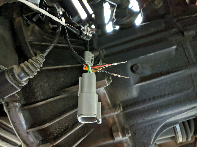
Toyota Oil Pressure Sender
-
I've only seen their NPT sender, and those Honeywell 150psi senders don't have a BSP option according to the spec sheet. I'll check in with my local fittings & hydraulic supply shop to see what we can come up with. Thanks all!
-
Spent a long time measuring this sensor. The resistance does not change when wired in a way that is consumable by an analog input. I should give up on analog input. Even if I can produce PWM from this sensor, I have to link it somehow to "Oil Pressure." I can measure frequency in voltage, but this crazy thing seems to operate via using the voltage to operate the sender, and "send" on the same line by consuming some amount of current periodically. I.e., it toggles a potential increase across a powered line. Found the testing procedure in the FSM, it wants 12v. I gave it that and looked - I got a similar periodic blip in voltage, but it was only slight, nowhere near enough to divide down to get a reliable 1v digital boundary. It's hard for me to measure an in series resistance wave form, or graph an amperage waveform. I think I need to give up on using this sensor. It's going to be a real hassle finding one that'll fit this space!
-
A very fair request! Here's what I've tried: This was my first try, still seems like it should work... I've varied the resistance from 100 to 460. Via math, my sensor's resistance seems to sit around 66ohms regularly. This should work if it's doing something PWM-y, but there's no PWM activity from the multimeter (should read like 0.75hz with engine off) but if it's using the power incoming from the ECU to drive the sensor, maybe the built-in pullup is too restrictive. Tried a couple different resistors to get the original voltage graph to below 1v, but in no case have I observed PWM (even via multimeter) while this sensor is hooked up to a digital input. Am I wiring this wrong? :-) That would be great.


-
With the 100 ohm pull-up, the digital input does not fire. I've been told the transition point for digital inputs is ~1 volt. Look up at that first graph to see it doesn't really cycle that low with a 100 ohm pull up. Would be great if that were configurable!! The graph above could indicate a 66 ohm resistance when "on" or "low," so I'd need a 600 ohm pull-up to get to 0.5v when driven "low." With a greater resistance on the pull-up, the modulating behavior is not observed anymore, but the input is still rock steady while running (despite great rpm swings at operating temperature) as observed by AN4. Either the ECU's +5v is overloaded and cycling with a 100 ohm load (seems unlikely) or the current offered through a 600 ohm resistor is not sufficient to charge whatever's in that pressure sender bulb and get the PWM on DI-1.
-
It's not 1/8 npt, it's BSP thread... You can do adapters, but darn it, there's already a sensor there and a wire to it :-) I'll try a digital input and see what's there - but seems like the analog input would have shown some change with a wide pressure swing... Definitely want to understand how to map frequency to oil pressure if this is the case! Check the log, it isn't floating - it cycles. +5v -> 100ohm -> AN4 and Sender -> Ground If Sender is Open, AN4 should be 5v. If I put 4.7k ohm to ground, AN4 should read 4.9v if the sender is open, right? What does that gain over just 5v without the extra divider path to ground?


