devan1811
-
Posts
21 -
Joined
-
Last visited
devan1811's Achievements
")
Newbie (1/14)
0
Reputation
-
thank you mate
-
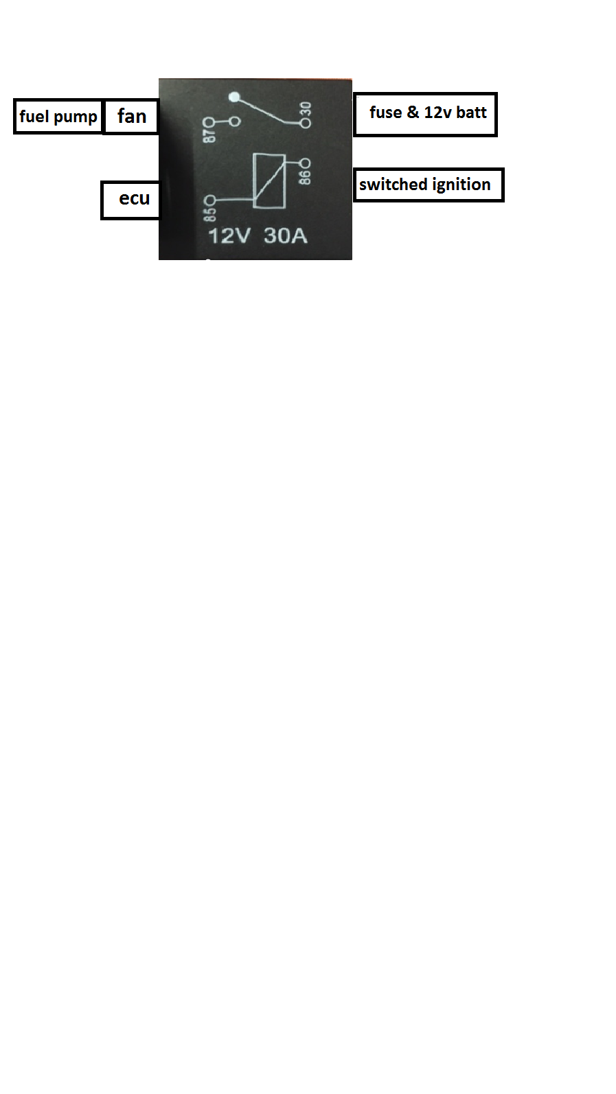
just want to make sure this is correct before doing something drastically wrong, wiring is not my strongest point... does this look correct?

-
Is it just a standard 4 pin relay I use? iv got a Revo-tec switch that I wanted to use so when the cars hot but its not on you can keep the fan running?
-
Monday I went to WGT Auto developments for abit of base mapping and everything was great, the only things I need to change is my cooling fan which is run off manual switch at the moment, but the tuner said to wire it directly into the ECU (it has the standard cooling switch). And the other thing is the fuel pump, again I have got it on a flick switch but I need it to go into the ECU, positive wire I presume? can someone explain how to wire them into the ECU wiring on a 76pin (4-3-3-3) SR20DET, is it just through the standard wiring itself on the plug?
-
So my SR20 is going to be given a base map so I can run the engine in on the 14th, I currently have fitted SARD 850cc injectors, but im now wondering if its worth me changing them back to the standard 370cc injectors so I can run the engine in and then at a later date when it goes in for mapping change them over to the 850cc's again? What would you recommend? and would they be able to base map it with 850cc injectors?
-
Having abit of a play around it turns out it's just the feed from the ecu to the feed on the BMW like you said adam, I thought I had to boost the signal bu that was from a standard ECU so using the link the output is 12v like you said. thanks for the help and support
-
sorry mate, The tachometer is fed by a signal from the ECU.
-
From the main C101 plug (loom) I found the correct pin from that and then had a read online and found that the standard SR20 ecu uses a 5V signal, but if your saying that the LINK G4 uses a 12v then I don't need the booster pack that I made. Im going to follow the wire direct to the tacho with a multimeter and make sure im getting 12v from there, I know I have 12v from the engine bay harness and from the Nissan cable now just nothing making the needle move at the moment.
-
Hi, so I have a E30 bmw with a Nissan SR20 (76pin ecu) and I am trying to get my standard rev counter to work in the E30, I know the S14 ECU tacho signal wire uses 5V and the BMW needs 12V, so I have my myself a board that allows be to boost the 5V to 12V, but, still no joy. Is there any way of getting this to work through the G4 setup or anyone know of a way to get this working correctly? Many thanks
-
I have two fault codes when connecting my ECU an can't work out what it is.. the first is code 11 & the other I think is 46? on the XS plug I have the +5V out not connected to anything... could that be it?
-
Thank you for clearing that up for me! really appreciate it.
-
 devan1811 reacted to a post in a topic:
Wiring a AEM Wideband into a G4 link
devan1811 reacted to a post in a topic:
Wiring a AEM Wideband into a G4 link
-
The Link intake air temp sensor and also a MAC 3 port boost solenoid, what is the best way to wire these in? I presume the MAC solenoid wires into the original boost controller wiring is that correct? Just need help on where to wire into as I'm not the best when it comes to this if someone can help with this as I'd like to get it finished today, thank you in advance


-
hi Adam, thanks for the help I have now sorted that. I was also meant to ask you about the Link intake air temp sensor and also a MAC 3 port boost solenoid, what is the best way to wire these in? I presume the MAC solenoid wires into the original boost controller wiring is that correct?
-
great stuff thanks for your help. I can presume that I no longer need the standard Lambda sensor now I have this fitted?
-
Thanks for the help mate, so with the black not to earth it to the body but a negative on the fuse box is that correct?