DaRKNT
-
Posts
8 -
Joined
-
Last visited
DaRKNT's Achievements
")


-
Hi All, I currently have a EVO8+ and am looking to upgrade to an EVO8X. As per the data sheets, I understand that the Plugin Range of G4X ECUs have the following I/O: - 8 x High Current Injector Drives (suits high impedance injectors) - 8 x Ignition Channels - 8 x Auxiliary Outputs (All PWM capable). - 11 Digital Inputs (All capable of reading frequencies up to 10kHz) - +5V Out - 4 Temperature Inputs (Configurable pull-ups on ANT1&2) - 12 x 0-5V Analog Inputs - 2 x Trigger Inputs (Reluctor, Optical or Hall Sensors) - On Board Baro - 3 Axis Accelerometer Looking over the EVO8X manual, I see the following is pinned: - 8 x INJ - 8 x IGN - 10 x AUX (Including AUX 9/10 for DBW) - 10 x DI - 3 x AN Temp - 10 x AN Volt From my previous research with my G4+, the balance of the I/O is available on the bottom board however not pinned for the plugin ECU - the "missing" I/O can be made available if wires are added (refer link below) My question is - is this also the case with the G4X? i.e. can the missing DI11, ANTemp 4, ANVolt 11 & ANVolt 12 be added in if the wires are run to the bottom board? Am I able to order the ECU with this already completed? What is the additional cost?
-
Hi All Seeking some guidance from those running a DBW set up in their cars. In preparation of installing my E-Throttle setup, I'm trying to work out how to get things interfacing with each other, one of those items being the ACD/AYC system - particuarly the 4WD ECU. As I understand it, the 4WD ECU requires a TP input - how does this work when the conventional TPS is removed in lieu of a DBW TB+Pedal set up? Additionally, how do the EFI ECU and the 4WD ECU talk to each other? Is it as simple as the 4WD ECU inputs being spliced in from 0-5V (ie. 0-5V from TPS being spliced somewhere and fed into both ECUs?) or do they communicate via a more sophisticated setup? Thanks all!
-
Can a Evo8+ G4+ (With E-throttle) have additional analog inputs added? Alternatively, can a DI be fed 0-5v? I too have run out of inputs on my G4+ having gone E-throttle and wiring in TPS Sub/Main and APS Sub/Main. I still have a number of pressure and temp sensors I wish to wire in, and the remaining 5 channels doesn't provide enough inputs given some factory inputs also need to remain.
-
Ah that makes sense - somewhat annoying as I'm stuck with a V1.5 board and I need an additional auxiliary output (Aux1-8) capable of PWM for my NZEFI fuel pump controller. I take it there's no way around this short of hacking up my factory wiring harness? Also, just a question on Aux10 - it's listed on the expansion connector as an available auxiliary out, however doesn't show up in the software as something I can assign a function to. I know it has something to do with the E-Throttle capability; however are you able to explain the use of the physical Aux10 pin a) with Ethrottle b) without Ethrottle
-
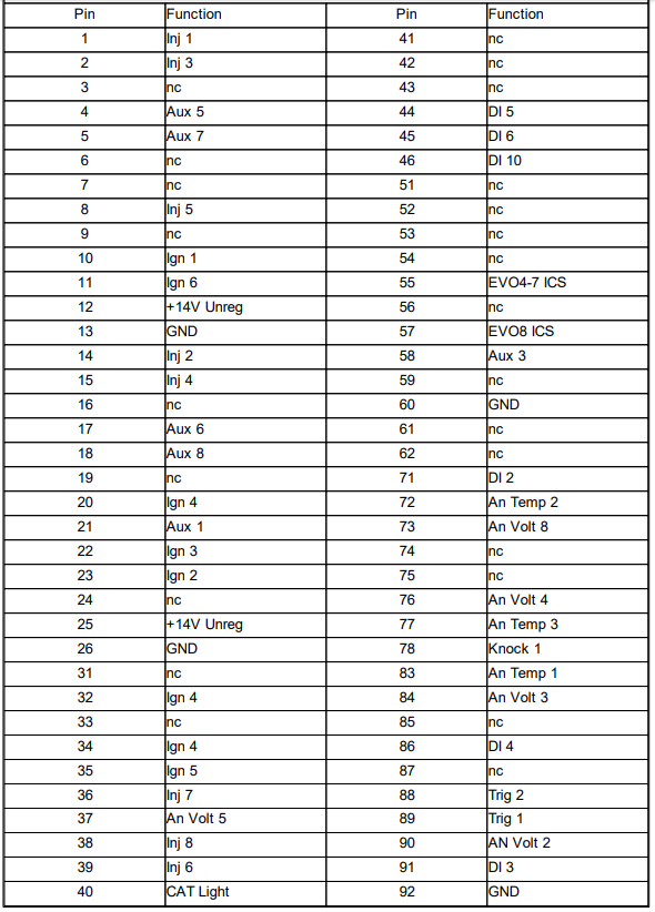
Hey Adam, With the CAT light - how do I go about assigning it to an alternate function? Going through my base map, there is nothing mapped as "Cat Light" in the inputs/outputs. Also, Cat Light isn't mapped as an Auxiliary Output etc (see pinout below). I've attached below what I have in my PCLink Help File vs What is on the most recent manual (Accessed through Link Product Page). Both are for PCB Revision 1.5+ and a G4+ with E Throttle. Just hoping to clarify which is the correct data. Thanks for your assistance!

-
Oh also, having gone through the mapping of pins and functions a bit more; I have a few more questions: 1) Pin 73 - AN Vin 8 - Not assigned to anything: Can this be assigned to anything should the stock baro sensor not be pinned here? 2) Expansion Connector 1, Pin 6 - Is this assigned to DI10 or AUX4? The plugin installation manual states it's AUX4 and PCLink Help documentation calls it DI10 3) Pin 40 - CAT light - my car doesn't have a cat light. Can this be assigned for use as something else? 4) Pin 46 - Is DI10 assigned here or is it assigned to Expansion Connector 1, Pin 6? - The plugin installation manual suggests that DI10 is mapped to pin 46, with AUX4 to EC1,Pin6. That said, the PCLink Help Documentation suggests that nothing is mapped to Pin 46, and DI10 is on the expansion connector. 5) Pin 11 - Is this mapped to AUX4 or IGN6? - Plugin documentation suggests IGN6, PCLink suggests AUX4 I've summarized my questions in the table below: Hopefully you can clarify, I apologise if I am understanding anything wrong.

-
Interesting - If I was to go to sequential ignition, which one of those pins would I connect my coil pack signal wire to? How does the circuitry/driving work given that the speed is controlled by two pins?
-
Hi All, I'm seeking to clarify what each of the above pins do and what they're assigned to. PCB Rev 1.5. I'm currently mapping my inputs and outputs and in doing so, I've realised that IGN 4 is mapped to 3 different pins on the stock ecu header. Could someone clarify if there's a revised pinout? If not, could someone clarify what each of these pins does? (Also, under pin functions, IGN 4 is not mapped to anything on the Evo VII/VIII) Thanks J