


EvilEvolution8
-
Posts
93 -
Joined
-
Last visited
Content Type
Profiles
Forums
Events
Gallery
Blogs
Everything posted by EvilEvolution8
-
Hello Guys, Any news about the release date ? Thanks
-
Ok cj... thanks!
-
The car is running now...wiring is just completed...I don't need to change the injector plug for switching from stock to IDs... I need to know only 2 things : - Stock evo injector with stock ballast resistor => What best Injection Setup settings? (Peak and Hold or saturated? what current? ) - ID1050x without ballast resistor => What best Injection Setup settings? (Peak and Hold or saturated? what current? ) Thanks
-
Hello Guys, I have a G4+ Thunder in my Lancer Evo 8. At the moment I have stock injector with stock ballast resistor. What config about Injection Setup ? (Now I have set to saturated (Peak 8A, Hold 0.1A) In the future (i think next month) I'll switch to ID1050x (without ballast resistor) In this case what is the best config for Injection Setup Thanks
-
Hi Adam....Sorry for delay.. I found the problem...the ignition fuse was broken...replaced the fuse...all works fine ... Engine now Is running . Thanks for your help
-
Ohh Sorry...i mean Fire Spark plug... So...if base timing Is way off..ecu cant fire Spark plug? Right ?
-
In the help file...its suggested to set it to OFF to avoid to inject fuel while settings base timing... Its right or I dont get It ? I Will try your advice for settings base timing
-
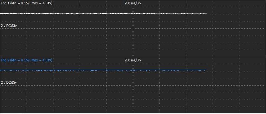
log and map attached base.pclr log.llg this is what oscilloscope says little update...like log says...after some seconds of cranking...rpm is around 172 but ecu not fire.. any suggestion?
-
Hello Guys, I have a Thunder on my Lancer Evo 8 with 12 tooth crank wheel and 1 tooth cam wheel (both using stock sensors) The ecu see the trig 1 signal and trig 2 signal (both green while cranking) but RPM = 0 Can you help me? Another question...in the trigger->calibrate...the trigger offset value is 1 and is locked...how I can modify it? Thanks a lot
-
Yes...Is B17...perfect...Is my same config. Enjoy your breakfast. Thanks Adam
-
Thanks Adam, I think you intend B17 not B7. So...shield and Ground sensor can be connected to pin Gnd/Shield...right? I have the same situation in my harness : - crank and cam ground and shield to A7 - knock ground and shield to B17 Is ok right?
-
Hello Guys, i have some questions about sensor ground and shield. 1 - I have CRANK, CAM, KNOCK with shield...can I join the three shield and connect these to pin A7 (Shield/Gnd) of Thunder ? 2- One sensor ground cable and one shield cable : can I join both and connect these to pin A7 (Shield/Gnd) of Thunder ? Thanks guys
-
Poor solution...whole exhaust will be extended by the thickness of adapter. All mounting points will not in position anymore.
-
I'm not going to use Lambda over CAN (thunder has two lambda controller). I'm going to use CAN only for I/O expanders (AN, DI, Thermocouple), dash or something like that. Is a "logical star point" but inside is a bus...like Haltech CAN HUB for example Like this https://www.haltech.com/overview-elite-dtm4-can-hub/ or like this http://www.mindsensors.com/frc/184-splitter-for-can-network
-
I thing i'm going to use the male connector AU-04BFFA-LL7001. I'll make a box with 8 receptacle connector AU-04PMMS-LC7001. i like to imagine a CAN like a LAN..with one star point (like hub or switch) and all devices connected to that point. In this way for me is simple to add/remove devices without touch the harness...with a 4 pin solution i can spread the power for all devices connected Is a bad solution?
-
I like the haltech can hub with 4 pin (power + ground + can lo + can ho) 4 pin DTM not exist a flange mount...only plug and receptacle. DT 4 pin exist in flange mount but is too big and too expensive. I Need a small 4 pin solution with plug and receptacle flange mount...solder or crimp is not a problem
-
Hello Guys, Someone can share info about the connector used for CAN. I need some plug and some receptacle flange mount ? (I appriciate with part number of pins, socket, plug ecc ecc) I would try to create my own CAN Hub Haltech style with same connector used by Link Thanks
-
Yes Adam...resistance based temp sensor usally arent linear....and the calibration of HT-010306 is really weird
-
Haltech in their ecu use 1k pull-up fixed. Is a little limitation...haltech HT-010306 is a linear fluid temp sensor (3v = -30°C, 4.1v = 150°C)...now i have to use one of Cal 7-8-9-10 insted one of Cal 4-5-6. Is not a problem...but is a little limitation...i think should bel correct have the possibility to do this.
-
Why linear calibration (Cal 4-5-6) are not available for temp sensor?
-
Thanks Brad.
-
Hello Guys, I have two type of fluid temp by haltech : HT-010306 and HT-010304. In the datasheet haltech provide the calibration in Volts...not Ohms...I can use these data into G4+ ? The datasheet provides a pinout too...but I think that in the 2-pin temp sensor the pinout is not relevant right ? Thanks
-
Perfect! Thanks a lot Adam.
-
Can I use AN temp 3 ? AN Temp 1 and AN Temp 2 already used for ECT and IAT.
-
Thanks a lot Adam, Pull-up disable ? Thanks
