cj.surr
-
Posts
71 -
Joined
-
Last visited
-
Days Won
3
Content Type
Profiles
Forums
Events
Gallery
Blogs
Everything posted by cj.surr
-
So, if I'm reading the chart correctly, only DI 1-6 are available? But they are available in two separate speed units. Seems like there is no way to see if a DI is on/off (switch input). That's disappointing because there are a few DI states that I would like to display on my dash (T/C switch, water/meth level switch, log switch, clutch switch). Also some other ones that would be useful are EGO correction, Lambda target, Boost target, fuel consumption (something that could be used for MPG on dash).

-
Are you choosing to "save layout as" from the layout menu?
-
I am annoyed by this problem too. Except for my Xtreme ECU, it is missing DI speeds 1 through 4. Any plans on adding this? I'm not sure if it's a Realdash issue or serial stream issue. Also the ECU specific gear detection does not seem to be displaying correctly, despite it displaying perfect if connected in PCLink
-
5.6.7.3632 dll version 3600
-
I have been noticing file corruption happen several times, but I haven't nailed down exactly when it happens. PCLink doesn't show any errors when opening the file. This was the sequence today when I noticed corruption. I have been using Google Drive to sync files between my desktop and laptop - I feel like this may be the source of the problem. - At 12:27 PM I save a tune file on my desktop and it's uploaded to google drive -At 5:06 PM I start my laptop up and it updates the tune file on my hard drive. I then connect to the ECU in the car (PC link opens current tune file loaded on ECU) then select file>open>saved tune file. I then store the tune and hit save (F2). I have both of those tune files attached. The tune file from 5:06PM has at least a few tables corrupted. I do not know if the corruption occurred during file update from Google Drive, or upon connecting with the ECU. Before: Cal 10 Table After Cal 10 Table: Before 5D Fuel: After 5D Fuel: Before Boost Target 1 After Boost Target 1 There might be more corrupted tables, but that's what I've found so far. Here's the weirdest part: After storing the tune from 5:06pm on the ECU and driving the car, The ECU is still pulling the original values from the 5D fuel and Boost target tables, despite the corrupted values being shown in the tune. This is not the case for the CAL 10 table, for which the ECU is actually using the corrupted value (showiing 1000% instead of 100%). Part of the same problem seems to be corruption on Virtual Aux 8, which has occurred multiple times and apparently also before 12:27pm today. I have both values set as 220kpa, but during curruption, they change to 22.0 (unitless). I am not able to get units to show again unless I change the input channel and then change it back. This does effect ECU function- The virtual aux activates at 22kpa instead of 220 kpa. This has really thrown me for a loop before. OK, so that's a pretty big mess all over. I know the obvious answer is to try to stop using Google Drive, which I will. But it doesn't seem likely to me that Google drive could solely be corrupting the file consistently like this. so I'm interested in hearing some ideas. Thanks CJ E28 0506pm (laptop).pclr E28 1227pm.pclr


-
I have used the IC and circuit that Richard posted with good luck. Thanks Richard. I did seem to have some intermittent operation before tying the J1-5 pins to ground (left open initially). I'm not sure if that's necessarily what fixed it though.
-
I wouldn't say the DC table is perfect, but it's about as close as I can get it. (IWG on a big, fast spooling turbo being fairly inconsistent). The I-value is pulling about 2%, not a lot. Seems like it wanted about 19% DC to hit target, and in my WG table it was 21%. I think the problem is that when transitioning into Stage 2, the DC started at 26% because the P-value is immediately being applied (Table value is 21%). It tapers down towards 20% but since the WG has a delay (at least a few tenths of a sec), the higher DC initially does contribute to overshoot.
-
Unfortunately the log is too large to attach so it's shared here: https://drive.google.com/file/d/1cpi8_mGRGqu-0M3mX6lqFkx4wJH-lcbG/view?usp=sharing Thanks E28.pclr
-
I'm having an issue trying to dial in the PID settings for closed loop boost. I get a slight boost spike on spoolup. I think it is because the P-value is adding duty cycle immediately when the boost control transitions from Stage 1 to Stage 2. This correction doesn't make sense because the wastegate is transitioning at this time and any corrections will be delayed. If I lower the P-value sensitivity, I don't get all of the high RPM correction that I need (my setup is prone to creep). Are there any recommendations for working around this issue? It seems to me like there should be a delay before correction when transitioning between Stage 1 and 2. And/Or, separate P-value sensitivities set for Stages 2 and 3. Thanks CJ

-
I see, I wish that it would always ask if I wanted to load write the changes to the ecu, no matter how large. Because when it just loads the config out of the ecu and doesn't notify about anything, it's easy to think there were not any changes in the tune file. Then you carry on, tuning the config loaded from the ecu, until you realize there is no filename associated with the open tune file. Then you have to open the old file and see what's different, plus the changes you've recently made to the config file that was automatically loaded.... I've lost a good bit of time this way. If it's not possible for PCLink to ask if you want to load a tune with large differences, there should at least be a dialog that notifies what's going on (tune uploaded from ECU is replacing the open tune).
-
Bump, nobody else having this problem? It happens at least a couple times every time that I try to tune the car. Is there a way I could send a debug file of PCLink?
-
Ah, thanks for the replies. I figured that it would apply an exponential trendline... I can figure it out from here then. Just so the info is out there - The sensor is an IAT for BMW M52/S52 (US). I plotted it out against some values that I measured, and it seems to be a Hella 6PT as you suggested, Adam. It seems like thermistors do not follow a perfect exponential trend. Thanks CJ

-
Since switching to Link ECU, I have noticed that my IATs during driving have seemed higher than they should be. Around room temperature, the calibration is close. But when I expect IAT to be about 100F cruising on a hot day, The ECU was reading 130F. This was with the same calibration numbers as my old ECU (ohm scale). With the car having been turned off for a few hours, I would expect IAT to be slightly lower than CLT. However, IAT was about 20F higher. I tried converting my ohm values to Volt values (I'm using 1kohm internal pullup and assuming 5v reference is used internally). I found that when I plugged these values in, the IAT immediately dropped from 120F to 88F (following pictures were less than a minute apart). Obviously, we would expected both calibration methods to give the same reading. I tried inputing with F and C, both gave the same result. I have only gone for a short drive, but it seems like the IATs are more what I would expect. Unless I messed up my calculation, it seems to me like there is an issue with the Ohm calibration function. My spreadsheet is below. V = 5v * (R1/(R1+R2)) R1 = sensor ohm value R2 = pullup resistor value E28.pclr


-
Having this issue with PC Link ver 5.6.7.3632 Sometimes, when I have my tune file open and PC link connects to the ECU, it will close my tune file and open the tune file stored on the ECU. It doesn't bring up any dialog before doing this. The tune file name/path in the header of the PC Link window disappears when this happens. I haven't figured out exactly when this happens, but it seems to do it more often if I have been away from the car, changing settings.
-
Just wire the relay(s) low side to an Aux out as a "fuel pump" and it will automatically turn off the relay if engine RPM is 0.
-
This fixed it! Inlet/lh position is now pretty much perfect. I get about 7-8 errors on startup but nothing after that. (usually a couple missing teeth and then some "6th" and "8th" pulse erorrs - whatever that means). I attached a log, it doesn't seem like there are any problems. My main question from the other thread still remains, though. How do I know if the engine has fallen back on batch fire/wasted spark (if it can at all)? Or do I assume that an "OK" inlet/lh signal means the engine is sync'd? Log 2019-07-15 11;18;53 pm vvt test success.llg

-
The flow sensors for water meth are pretty pricey. The Aquamist one I was using was also very restrictive for my high flow (1500+ cc/min) setup. I recommend a simple 0-5v pressure transducer between the solenoid and the nozzle. If you have a leak or pump problem it will be visible as a pressure drop. Your aux input can be configured to lower boost if WMI pressue is not high enough. Also it is possible to calculate flow based on the pressure differential across the nozzle (WMI pressure - MAP) and its flow rating.
-
Ok, thank you. I will try this later. I am confused why I need to use VVT settings at all, I have been told by Simon that I should not be using VVT settings with a simple on/off VVT. Are you sure? I know that if you test it during assembly with compressed air, it actuates about that fast. But I am looking at log files from 3 different M5x-based engines and they all take about a full second to fully engage. I know at least one of those (mine) has fresh vanos seals, I would assume the other two cars do as well. I now see that it's possible to interpolate between two VE tables based on cam, which I am excited to try. I think that will work very well if we can sort out the cam signal.
-
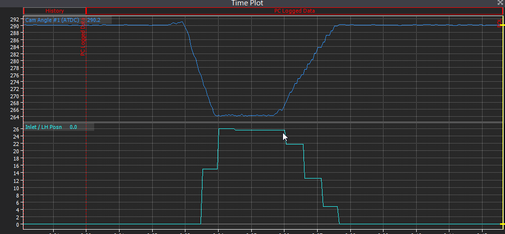
The Main trigger mode is generic 60-2 VVT was previously off (as recommended in my other thread). I turned it on to change filtering to 1 (from 4) and it has solved the delay problem but not the update frequency problem. Please see screenshot below. It's a PC Log, main rate is set to 20hz. Also I think you can tell from the steps that it isn't a log rate issue, but a parameter update issue.

-
I am having an issue tuning fueling because the parameter that references cam position lags over a second behind the actual cam position reading. It is also coarse and updated slowly. See the image below comparing the two cam position parameters (they are inverted because the "inlet/ lh posn" is absolute. "Cam angle #1" is much more precise but it cannot be used as a table axis. I need this because the Vanos on my S52 engine takes a full second to engage, and it can affect VE as much as 20%+. So I have a 4D fuel table that looks at cam angle to account for the transition time of the mechanical VVT. There is no way the "inlet/lh pos" parameter can work for this.... It's even slower than the mechanical unit itself. Can the "inlet/lh pos" parameter be changed so it does not have a delay and is more precise? It seems fairly useless this way. Thanks Log 2019-07-13 1;32;51 pm CAM POS TEST.llg

-
Why don't you see it being added? There's nothing overly complicated about it - it just averages a few sensor signal values. 10 year old Megasquirt software allows you to set an individual smoothing value for each input. Restrictors are not always practical/effective to add, such as in a water injection pressure.
-
How do you expect the ECU to change boost level if you're not using it to control boost? Closed loop control or baro compensation should be able to even this out for you.
-
OK, so I now have it set up as you have described. Generic 60-2, VVT off, Trig 2 VVT off, Cam Level. It seems to run fine. No trig 1 errors yet. I have a few questions and concerns now... 1) It does not seem like anything has changed with turning off Trig 2 VVT except: It doesn't look like it checks for Intake Cam signal errors and I can't read cam position (I would like cam position to be an axis on my 4D fuel map - one of the main reasons I switched to a Link ECU) 2) It does not seem like continuously variable VVT would have a chance at working (considering the signal error on cam position when VVT settings are on). I am considering retrofitting a PWM VVT valve that should allow me to have continously variable VVT. Since it should all be technically possible, I'm still curious why I should be getting errors when VVT mode is fully enabled and all settings seem to be correct. 3) How can I confirm that the engine is running sequentially and not fallen back on batch fire (if it does that at all)? I will spend a lot of time tuning the fuel map in the near future and I know that not having it firing sequentially can affect low load. Thanks CJ
-
I set this to off and I get "no signal" error on intake/lh. It seems to run poorer, as if sequential is not active. edit: that was with "cam pulse 1x". I will need to try it with "cam level" later.
-
OK, I'm going to recap, because this seems to be getting confusing. Generic Multiwheel 60-2 (cam 1x pulse) - RPM signal perfect, i have a hundred miles in and I haven't noticed any hiccups, cam error piles up (extra pulses), cam angle reading is solid. If I set Trig 1 to "rising", then I get occasional RPM spikes Generic Multiwheel 60-2 (cam level) - seems the same as cam 1x pulse S52 trigger pattern - Seems to be for a wheel of different teeth # - I get erratic firing and RPM value when changing base timing - no start S50 Trigger pattern - seems to run exactly the same as generic 60-2 (cam 1x) M52 Trigger pattern - also seems the same as generic 60-2 but requires crank offset of +30 instead of -325. Also I get different values for cam angle #1 and #2 - I assume it is expecting a dual VVT motor when mine is single Trigger scope looks fine to me, I have checked dozens of times and it always looks the same. I feel like the cam signal is not the problem here. I am assuming it does not matter if cam test mode is on or not. I am leaving it on so I can see absolute Cam angle as I change settings. I have VVT off, and cam-switched set up ( am angle test still seems to work with VVT off) For all of the working trigger patterns I seem to get a steady cam angle #1 reading of 290deg. So I have 290deg ATDC in the TRIG 2 VVT settings menu along with "inlet/lh" I'm not sure this is important but I have 12v power going to both my cam and crank sensors as it is from the factory. Thanks CJ