


JMP
-
Posts
330 -
Joined
-
Last visited
-
Days Won
16
Content Type
Profiles
Forums
Events
Gallery
Blogs
Posts posted by JMP
-
-
I always have a discussion with the tuner before handing the car over to be tuned, if they insist on password protecting their "intellectual property", I take the car elsewhere.
With one tuner in particular on a previous ECU of mine, when I got access to the tune it was very obvious why they password protected the maps with the extremely poor quality of the tune.
-
how do you have your triggers configured? I had zero issues with my vvti 2J
-
upgrade the firmware
-
put one in a local car and the gauge goes down in quarters unfortunately, same as when you remove the stock ECU and wire in an aftermarket ECU that doesn't talk on the Toyota multiplex bus
-
looks backwards to me now. This pic is from the trigger scope section of the help file showing a normal trigger1 waveform

-
Dave, are you sure trigger 1 is reversed? Looks to have a slow rise on the missing tooth and falling through zero
-
good work
")
When you pull something apart, put it back together again and it doesn't run right, it's usually a physical problem. Messing with the ECU is the very last step you'd take when it was running perfectly before pulling it apart
-
do a smoke test on it, still sounds like a vac leak to me
-
no vacuum leaks on the plenum?
-
I'd be checking the loom/terminal integrity for the TPS. I've seen plenty of old Toyota looms where the insulation breaks down or you get corrosion up the wiring under the insulation. You can also watch the runtime value screen to see if noise is being introduced to the signal
-
the G4+ based evolink's are the new "i series" plugins. They just removed the sticker from the rebadged vipec version
") Functionally identical to the i44/i88
Functionally identical to the i44/i88 -
There's not much work to change from the vipec v44 based plugins to the new G4+ plugin's, I did exactly that with my Subaru to get the VE based tuning, knock control, OBD2 output etc
-
In your map, the trigger mode is set to a 4cyl 2nz... You need to change that to 'Toyota 1JZ V VTi', then set the trigger offset to 205deg in the calibrate page
The Trigger 2 vvti offset needs to be set to 170 ATDC
-
you've got the coils wired incorrectly. Wire them:
IGN1 to Coil 1
IGN2 to Coil 2
IGN3 to Coil 3
IGN4 to coil 4
IGN5 to Coil 5
IGN6 to coil 6
Your firing order table is correct
from the help file:
When wiring an ignition system using direct spark, the firing order of the engine is not important as it will be entered into the ECU via Vi-PEC Tuning Software Tuning Software.
Ignition Drive 1 must be wired to cylinder 1 coil, Ignition Drive 2 to cylinder 2, 3 to 3, etc.
Same goes for the injectors:
The firing order of the engine is NOT important at the wiring stage as the firing order will be entered into the ECU via Vi-PEC Tuning Software Tuning Software. Wire each cylinder to its corresponding injector drive number (wire cylinder 1 injector to injector drive 1, 2 to 2, 3 to 3 etc...).
Set the 'Injection Mode' to 'Sequential' when using this configuration.
-
With my vvti 2jz running yaris coils direct fire I ran with the Trigger mode set to Toyota 1JZ V VTi, in the calibrate screen I had the trigger offset as 205deg
The Trigger 2 vvti offset was 170 ATDC
-
The Throttle position sensor has 4 wires, 5V (VC), VTA, VTA2 and sensor ground (E2), the pedal position sensor also has 4 wires with the same 5V and ground along with VPA and VPA2.
Wire VTA to AN Volt 6 and set to TPS Main
Wire VTA2 to AN Volt 5 and set to TPS Sub
Wire VPA to AN Volt 3 and set to FPS Main
Wire VPA2 to AN Volt 2 and set to FPS Sub.
This is also detailed fairly well in the help files

-
yes, use the vvti trigger setup from the help file then do calibration with a timing light as per standard procedure.
-
-
that base file is non-vvti and direct spark, but easy enough to reconfigure for vvti triggers and waste spark ignition, just follow the info in the help file
-
have you got the reluctors wired correctly with regard to polarity?
-
Seems to be working fine for me, have been using it since the previews for a couple of months
-
My understanding is the plugin is intended for Supra's with single turbo conversions. Someone from link would need to confirm.
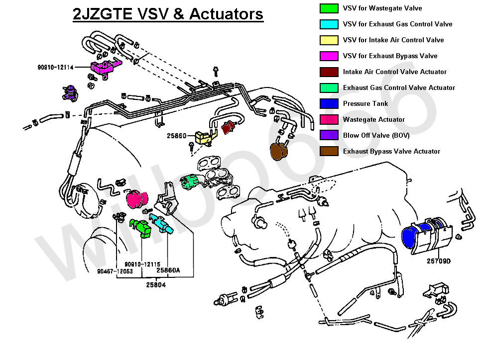
When you look at the pinout and function information for the supra plugin in the installation manual and help file, not all the twin turbo VSV's and actuators are wired. Only 1x wastegate control solenoid on Aux4.
The high level pic of the stock system with the various control systems is this one:
http://wilbo666.pbworks.com/f/2JZGTESeqTurboSystemTesting.png
A more detailed explanation of how the stock system works is here: http://www.max-boost.co.uk/max-boost/supra/turbo.htm
If you're willing to wire your spare outputs to the system and have a crack at programming the logic to make it work like factory, good luck to you
I took the simpler path with a GT35R on my vvti 2J
-
The vvti motors use a different type of ECU loom plugs so the non vvti ECU doesn't physically plug in. Workaround is to use one of the universal ECU's and a fields-type adapter harness to make a plugin loom if you don't want to mod the stock ECU. For the twin turbo setup to work like factory, you will need to wire in all the control solenoids and then attempt to program the logic to control them like factory. Or you can do a simpler TTC setup which is easier to control electronically: http://mkiv.supras.org.nz/articles/andy.htm
For reference, twin turbo info: http://wilbo666.pbworks.com/w/page/65646659/2JZ-GTE%20Sequential%20Turbo%20System
Additional vvti and non vvti wiring info: http://wilbo666.pbworks.com/w/page/37134465/2JZ-GTE%20Engine%20Wiring%20Main
-
JZX110 is a drive by wire vvti 1jz with waste spark ignition same as the vvti 2J. You can use the Supra basemap fuel and ignition maps as a guide, are you leaving the stock ECU in control of the throttle and auto? Wiring in a new intake air temp sensor in a post intercooler location also?
You can use the attached file as a guide, will need all the inputs/outputs reviewed and reconfigured based on how the patch loom is pinned. Would also need the usual DBW configuration/calibration.

")
") Functionally identical to the i44/i88
Functionally identical to the i44/i88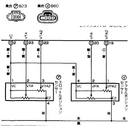

Altezza OBD2 wiring
in G4+
Posted
Open the PCLink help file, navigate to or search for the "ECU to OBD-II Port Wiring" page, all the info you need is there for the CAN bus wiring.