Davidv
-
Posts
326 -
Joined
-
Last visited
-
Days Won
32
Content Type
Profiles
Forums
Events
Gallery
Blogs
Everything posted by Davidv
-
Something I've found handy for my idle, for those situations where it stalls when car is coming to a stop. Is to have an idle rpm table that sets a higher target idle rpm if car is going over say 5kph.
-
The Hitachi MAF sensor that's used for the R35 and similar can flow some pretty big numbers without topping out. (Which makes sense as it makes some fairly decent HP out of the box) It's only really for part throttle and really low load that you need a smaller pipe for decent resolution, if you're just using it for observational purposes at full throttle then you can bang it in a big pipe with no issues. But you can find pipe size that results in hp maximums easily from the R35 people. EDIT: Although thinking about it, I think they might use two MAFs and two pipes on those? I'm just going through the motions of installing a dual VVT engine, will be interesting to have a play around with the exhaust side cam too.
-
Yeah only intake cam, and NA motor.
-
Hey, (Disclaimer - not a subaru engine just some general vvt stuff) I ran a test where I would do a full throttle pull at "zero", advance the cam 5 degrees, then do this all the way through to 50deg. Using a MAF I logged the airflow readings of each cam angle to see which gave the highest amount of airflow through the rev range. What I found was that there was nowhere at full throttle where absolute zero gave the best power. Most of the time through cruising conditions you're advancing the cam a bit too. Zero position of the cam (in my case at least) is essentially only used at idle. So both zero and the advance amount are fairly arbitrary, as in reality you're just setting it to wherever it wants to go. On this graph, whatever produces the highest results up the page gives highest airflow into the engine. The colour scale is degrees cam advance.

-
Very cool, do you have any dyno plots or videos of it running? We've got a V12 Century, almost completely silent in standard form!
-
Ahhhh I didnt make the link that TC is thermocouple! I was eyeball scanning for EGT. Thank you Richard.
-
Hi, I've been cobbling together a canbus EGT board so I can look at EGT per cylinder. I see that there's lambda per cylinder available via can, but what's the reccomended method for EGT? Dont think it shows up at all. Was hoping to avoid using the 8 generic can-analog inputs as I've got these set aside for other stuff. Also it would be nice if these could be labelled like regular analog/digital inputs. So they're not just called Can-AN1 etc as I forget what they do sometimes. haha.
-
Hi, On the default settings I've broken a few sets of E-throttle gears, and I've seen a few other people mention similar. (I've busted 3-4 gears already) So I've been looking at ways to mitigate this. Initially I started just looking at the throttle mapping itself, setting the max and min to 2% and 98% so it's not trying to bang into the end stops. But then realized that the e-throttle clutch can be used to help as well, by softening the clutch near the end stops. So I'm using a table like this, and havent had any breaks since: Perhaps it might need fine tuning on an individual basis to make sure it's not slipping too much near the extremities, but it's tested as working well tracking to its target even with high motor DC / fast accel/decel rates.


-
Most modern ECUs are very capable now, we live in a great era for ECU ownership! One thing which swayed me towards a Link though. Is, download all of the tuning software for each ECU you are considering. Have a nosey around. Is it intuitive? Is there a help file etc? Does it take bloody ages to load? Do you like the look of it? The PClink help file is one of the best and most helpful documents I've ever read. Haltech didnt stack up for me, because it's more expensive for what seems like more features and a less scientific approach to some features. Although, it's definitely true to say that whatever your tuner's preference is. Will save you some headaches and $$$ for setup and install if they know the product back to front already. A good tuner will be capable of tuning any type of ECU, but pandering to their personal preferences will likely save you some money if that's a consideration.
-
You could have a look at the knock sensor signal for each cylinder. When an engine is misfiring, that cylinders background noise level on the knock screen can be lower. (Depending on the engine and knock sensor fitted I guess) Also the engine rpm signal can look rough. There's no monitoring of the coilpack return signals though.
-
Yeah the transciever is miniscule though, doesnt increase footprint: https://www.tindie.com/products/Fusion/dual-can-bus-adapter-for-teensy-35-36/ The refresh rate is good especially when optimized to minimize pixel writes. But if youre spamming it with lots of fast moving stuff or your code has a lot of unnecessary writes it can chug a bit. Moving over to realdash on a tablet is a whole bunch less work to be fair. But this is a learning exercise for me as much as anything else. The start up time, for me, is something that needs to be super snappy. Thats where a microcontroller is so good. I want to migrate my project to a twin core stm32 and a custom board at some point. So i wont need nextion it can control an lcd panel directly. But this is a huge amount of work and ive got lots to learn in the meantime.
-
Yeah I started out using a mega but it was starting to chug. If there are any instances where you need/want floats then youre gonna grind to a halt. Teensy is just so much faster, instant boot time compared to a pi, floating point and 32 bit calcs no sweat. Plus the dual onboard canbus of course. In your case PLA might be fine, I actually drove around for a month or two with it - it was just a whole day of left out in the beating summer sun in a sealed car that did it. But have redone in petg which should be good. If youre ever looking at getting a screen go for the nextion options over 4dsystems. Cheaper and much much much faster. 4d screens only have an 8 bit processor and have a crappy slow refresh rate.
-
Yep it is a plug and play swap for factory dash, and everything works. The cruise control ignition trim, I've had it automatically build some surprisingly sane ignition tables just from starting at 10deg everywhere. But still fine tuning it. I had my 3D printed housing get a bit melty left in the car on a super hot day and sagged on its mounts and warped a bit. So I've reprinted it with a more temperature resilient material. It's a bit of a mess behind the cover as its a hodge podge of lots of parts. but I'm just in the process of consolidating everything onto a single circuit board. Still heaps of work left till I'm done, but, was an awesome milestone to get it working as a plug and play.
-
I started out building apon the excellent work of @paulr33 with his canbus example code that he put in a post here and also on his website: http://www.paulr33.com/?page_id=16 I'm not using any of that initial code anymore as I moved from Arduino Mega to Teensy 3.6. But it helped me understand the basics immeasurably.
-
Ages ago I was using cruise control to do some road tuning for best fuel economy. I'd drive a set piece of road at a set speed. Then had digital inputs on the dash that added different combinations of ignition timing. So I'd go do a run at XYZ speed, which has lots of ups and downs in it to vary the load. Record a log file. Then come do that same thing again, with different amounts of ignition advance added by the switches. This showed clear as day in the CC per min fuel usage logs, and TPS, which was best. So I took this a step further and made an arduino canbus unit that would wait for certain conditions to be met (cruise control on,steady driving no tps movement) When cruise control is turned on, a virtual aux is triggered by the Teensy which sends a digital canbus input to turn on a 4D ignition table that has an analog canbus input as the load axis. Then the Teensy has a full separate ignition table in it, and outputs the can value that represents ignition advance for the table. It would collect 100 samples of fuel economy. Advance the ignition 3 degrees. wait for conditions to stabilize again. Then collect another 100 samples. Then it would compare the results of the test. If the results were better above a certain margin, it deinterpolates the current load/rpm ignition timing addition back over the 4 cells that its interpolating from. Then it checks that if there is any lower load area or lower rpm that has less ignition timing than this, it will update those values too. If the economy got worse, it would creep the ignition timing slightly back from where it started from, and do it again. Basically it's auto road tuning for MBT. (But only works in a fairly narrow rpm and load range, because you dont have cruise control turned on at 8000rpm WOT) So it iteratively builds up an ignition timing map on its own and keeps fine tuning it. Starting with 10 degrees timing everywhere, it builds up a relatively sane ignition timing map in about an hour or two which is really cool. But whats nice is that when the car comes to a stop I can store the values to Eeprom so they're not lost when car shuts off. So I'm also planning to shuffle the knock sensing logic over to this board too, so I can store long term knock trims instead of losing everything when car turns off. However, this then also scope creeped into a context sensitive plug and play digidash / 3d printed housing. With a whole bunch of other crap going on like auto dimming, changing screens based on what you're doing, xy plots, histograms, etc etc. Also takes all of the standard dash inputs like lights, indicators, etc etc. Work in progress! (Its for an 80s car hence LCD type look) Working through some bits at the moment like estimated range off remaining fuel, and things like that. Has been a good learning experience and I'm pretty happy with the results so far. Once the auto dimming became functional It's been really nice to drive with. Trust me though, you dont want to see the code hahaaha.

-
All good, no drama. Cheers
-
An example: Going through the options it looks like MAF is the only one with this quirk. I want to run one of the more modern MAFs which has a humidity sensor. The fact that Humidity outputs as a frequency isnt a problem at all, as theres no input for humidity so its frequency will just be a load axis on a trim table anyway. But the mass air flow signal is digital too, and mass air flow being mass air flow is pretty critical for the rest of the modelled fuel stuff to work nicely. If a frequency based maf doesnt work, not the end of the world to be honest.

-
The scale on the cal tables can only be volts or resistance... What do I do, for a DI when a cal table has been set?
-
I know its a bit of a bodge, but I've done this by using CAN inputs and outputs. You can output variables over can, do maths/programming/etc on your canbus device using the information, then send the variables back into the ECU. I do this to log a litres per 100km parameter into the ECU so I can view it in the logs with everything else (only cc per min is available otherwise) I've also used a canbus input as the load axis on an ignition table and had my device trim the ignition timing with more logic than is available on the ECU. Check out Teensy 3.6 and the IFCT library for it.
-
What's your load axis currently? If you are using MAP you might find its beneficial to switch over to a TPS based load axis at lower load where map is unstable. Out of interest do you have any logs you could post up? And what kind of intake is on it?
-
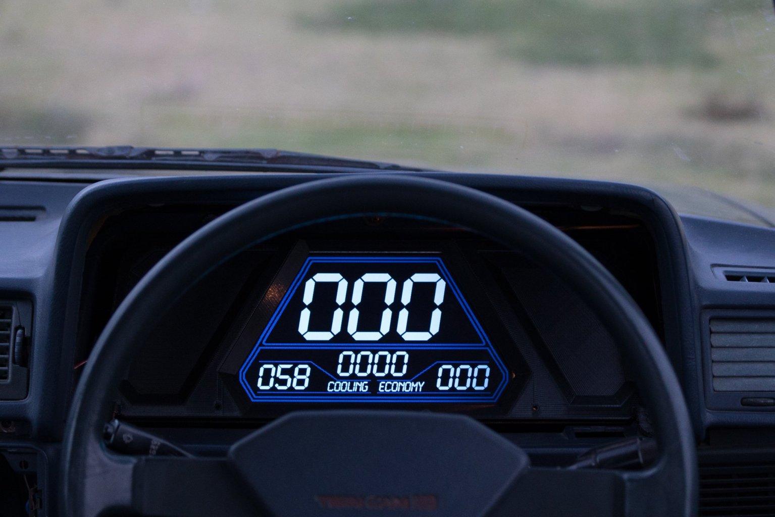
Since that last post spent a bunch more time working on the dash. Been trying to keep an 80s sort of theme to it while looking somewhat like it belongs in the car. It's now at the point where all of the factory dash plugs fit straight into the back of it, it uses some opto isolators to input all of the standard dash things like indicators, high beam, etc. It's got auto dimming on the screen which works great. It can log to SD card, read it back and draw XY plots or histograms or whatever. Learning a lot about interface design, and minimizing distraction. Although it looks plain with only a few things on it, when you turn on an indicator (or whatever) it flashes on screen as you'd expect. The digits for temperature turn yellow then red as you cross a certain threshold. Also building some contextual screens so that it shows you different information when you're racing vs cruise control turned on vs normal driving. Or whatever. So for example, when racing you only really want a tacho bar going from say 4k - 9krpm and only want to see temps or pressures if they're a problem. So show minimal stuff. If you've got cruise control turned on, you're likely more interested to see fuel economy data, estimated remaining range, trip meters and so on. Has been a bloody long project but feels good to be at the fun part instead of battling with trying to learn programming, trying to learn canbus, trying to learn arduino etc all at once! In other news I tried an ITB setup but results seem to indicate less power than factory setup at best of times, and when heat soaking, significantly less power. Sounds completely obnoxiously loud and looks cool though haha. Currently making a few different trumpet designs, will dyno to see which works best and then see what I can do to build an airbox around them to mitigate the temperature issues. But in the meantime, back to standard plenum because I quite enjoy the E-throttle/cruise control, and, well, it looks to make better power too!
-
Your mixture map is whatever your fuel table is. If you have two fuel tables, you need to go into the options and switch to that instead.
- 4 replies
-
- 1
-

-
- log file
- afr playback
- (and 2 more)
-
This isnt a Realdash forum, Link dont make it... Maybe contact them directly to see what support avenues they offer.
-
If youve got aftermarket cams you might be getting some overlap which makes your map signal unstable at idle. You could make a second fuel table that uses a virtual aux as a switch, so switches to an idle fuel map that's TPS based when you're below say 2% throttle and 1500rpm.
-
So long as the RX8 outputs two APS signals from the pedal then it will work fine that way. ECU just wants 2 TPS and 2 APS, doesnt care where they come from. Yeah you can setup a table to vary the e-throttle angle based on cold start etc so no ISCV needed. Just something to note, make sure your normal throttle map keeps the throttle plate away from the end stops, like if right to end stop is 100% travel then only go 98% or whatever. As otherwise you break e-throttle gears if it slams the stops (been there done that) If that e-throttle setup has an electromagnetic clutch like the Altezza system does, then you can run a PWM to it to soften the clutch near the end stops to reduce chances of damage.