Scott
-
Posts
2,257 -
Joined
-
Last visited
-
Days Won
70
Content Type
Profiles
Forums
Events
Gallery
Blogs
Everything posted by Scott
-
Can you confirm that there is one sensor per head, or two per head? The V7 to V9 engines has two sensors on one head, and one sensor on the other head. On the head with two sensors: One sensor sees a two pulses per cam rotation. This should go to Trigger 2.The other sensor sees four pulses per cam rotation. This should go to a digital inputOn the head with one sensor, this should go to a digital input channel. The crank position sensor will still go to Trig 1. If your engine is not like this can you tell us what year vehicle it came from. Scott
-
I think there are a few issues going on here, but if your trigger voltage is only 0.16v then Adam is correct, this will create a problem. The ECU will regard anything less than the value entered in the active trigger arming threshold table cell as electrical noise. To increase the voltage the sensor is seeing you can: reduce the gap between sensor and teeth of the wheelincrease engine speed at crankingreplace the sensor with a sensor that outputs a greater voltage for the same conditions.Scott
-
Hi Blaine, Thanks for giving this a go. If you look at the 'CAN' tab of the runtime values window, does the CAN module you are using have any errors? Scott
-
The rotary cut mode cuts the injection and ignition outputs in a particular order to suit a rotary engine. It is hard to say what the effect would be on a 4 stroke engine, there is the possibility that a fuel and ignition event could occur or overlap, this could be a risk to the engine. Scott.
-
Good work on the patch harness, sounds like things are going well. Scott
-
Hi Llewellyn, I'm guessing the 'Multiplier' and 'Tach Duty Cycle' settings have not helped? Scott
-
The problem is the auto gearbox. Not many aftermarket ECUs are able to control the auto transmission. One possible solution may be to do a 'piggy back' install. This is where the factory ECU (and transmission controller) are kept, and the Link ECU takes control of various ECU outputs. Generally these would be the injectors, ignition coils, fuel pump, and wastegate solenoid. The engine sensors get shared between the factory ECU and the Link ECU. Sometimes these installs can be troublesome. I recommend finding a local Link dealer and ask them if they've done an install like this before. Scott
-
Thanks for the files. It looks like the polarity of your trigger 1 signal needs to be changed. Can you do another log file of the problem, but this time use PCLogging? That way we can see all parameters. Scott
-
Adam is correct, changing the VE value (fuel table 1) or the charge temp value (charge temp approximation table) will have an effect on the value of 'Air per Cyl Estimated'. Scott

-
Hi Grant, yes that is mostly correct. On the G4 ECUs and early G4+ ECUs (basically any that used bottom board V1.1 or 1.2) pin 73 is An Volt 1. On the later G4+ ECU (any bottom board that is V1.3 or V1.4) pin 73 is An Volt 8. Scott
-
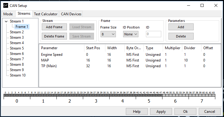
Good work. Ok, so you will need to wire the CAN H from the Link ECU to the white wire, and the CAN L from the Link ECU to the black wire. I have prepared a Link CAN Stream file to test if this is going to work. The file contains the Haltech CAN ID 360. Here is what the Haltech data sheet says: Here is how you will set up the Mode tab of the Link's CAN setup window: In the Mode tab select the CAN Module you have wired to the IQ3. Set the CAN ID to 864. The haltech data sheet uses a hexidecimal CAN value of x360, the Link ECU decimal equivalent is 864. Then move to the Streams tab of the CAN setup window, click on 'Stream 1' in the the left side of the screen then click the 'Load Stream' button. Now select the file attached to this post, and load it in. Now click the little arrow beside the word 'Stream 1' and you will see Frame 1, click this. You should now have your screen looking like this: Click Apply, and the OK. Now perform a store on the ECU. All going well you should now be able to see Engine speed, MAP, and TPS on the dash. Let me know how this goes. Once this is successful I can setup some more Link CAN stream files for you. Scott CAN ID 864.lcs


-
Hi Grant, thanks for letting us know. I've checked the base-map from our current release and this problem now seems to be fixed. Scott

-
I think the Idle ignition table will be creating some problems also. Normally the '0' column should be set to an ignition angle at which the engine idles nicely under normal conditions. This is because the idle ignition table is used instead of Ignition table 1, and not as a trim of ignition table 1. I recommend getting the open loop idle control as nice as possible before switching over to closed loop mode. The closed loop idle control uses the base position table (from open loop) as a starting point. Scott
-
Hi Dan, I've referred this on to the engineers, here is what they had to say: The "Air per cylinder measured" parameter is a value only from a MAF input. The "Air per cylinder Estimated" parameter is calculated from the MAP sensor. The engineers are happy to add "Air per cylinder Estimated" to the table axis options and will put it on the list. Scott
-
Ok cool, that is good info. Were you able to find out which pins were CAN H and CAN L? Scott
-
It would be ideal if they could supply something similar to this: That way we could see the actual data layout. And as the ECUs have custom CAN configuration it is highly likely we could replicate it. Scott

-
Not with a backfeeding problem, as the backfeed is through the activation coil of the relay. Scott
-
The GP RPM Limit table is able to protect the engine just as well as when closing the throttle. Regardless of which method is used the driver will be down on engine power and the engine will be protected. Streetenergy, as you mentioned earlier, the Link ECU is already able to switch e-throttle target tables, so if you want to use this method you can. Maybe you can have one axis of the e-throttle target table as 'AP(Main)' and the other set to a virtual auxiliary channel. You could then have the virtual aux channel activate like in this image: This does rely on you having the EGT values coming into the ECU over the CAN bus. You can set the actual temp value to whatever you think is suitable. As Ducie54 mentioned, an audio buzzer output could be a useful alert for the driver. Scott

-
The Aim dashes use Link ECU's "Generic Dash" CAN data stream. It is no problem to make the G4+ Xtreme transmit this. What I do not know is how you would connect the CAN bus (CAN H and CAN L) to the Racepak without their V-net Module. The manual for the IQ3 doesn't appear to give any clues to the pinout of the V-net connector. http://downloads.racepak.com/IQ3/IQ3_Manual_v2.pdf My understanding (which could be wrong) is that the 'Haltech IQ3' has an inbuilt V-net module, and so does not need an external v-net module. Where-as the 'Racepak IQ3' requires an external V-net module. If you find out which pins on a Racepak IQ3 are for CAN connection (if there are any) then it might be possible to get communication happening without a v-net module. Scott.
-
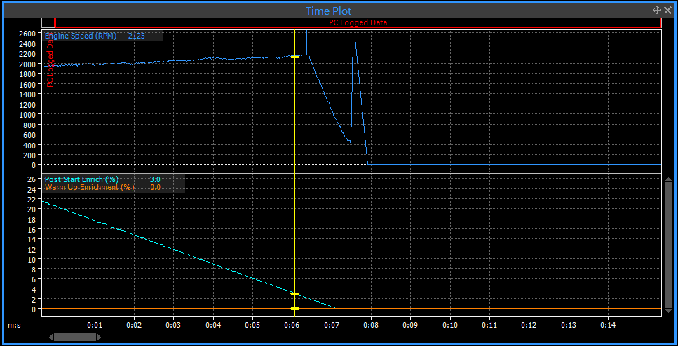
It's a little hard to say for certain what is causing this behaviour. I don't think it will be the idle system as I can see you're opening the throttle with your foot to allow extra air in and this still isn't helping. Here are some things I would check/change/try. Your ignition table load (Y) axis is set to MAP, but the MAP reading isn't changing (I'm guessing it's not connected). Try changing this to throttle position.I see the amount of trigger errors is increasing as you attempt to start the engine. Use the ECUs TriggerScope function to check the amplitude of trigger 1 and trigger 2 so you can set the Trigger arming threshold tables correctly. Do this at cranking speed and at 1000 rpm now, and do the higher rpms later once you have a good consistent start.Add in some warm up enrichment. At the start of your log I can see the post start enrichment finishes and the engines dies shortly after this. Scott

-
Hi John, Our ECU doesn't update the position/speed of the engine until the next tooth arrives. If the engine rapidly accelerates or de-accelerates between teeth the ECU only finds out about this when the next tooth is read. This can be a problem when the amount of teeth on a trigger wheel is very low. Most OEM trigger tooth counts seem to be in the range of 12 to 60 teeth. Scott
-
Hi Grant, An Volt 1 (Internal MAP sensor) should be turned off.An Volt 2 (pin 90) should be set to MAP and configured to suit your external MAP sensorAn Volt 8 (pin 73) should be set to Oil Pressure.Scott
-
It sounds like an ECU back feeding problem. This occurs when one of the outputs that the ECU controls is powered by a battery +12V instead of an ignition switched +12V. Are all outputs powered from an ignition switched +12V supply? Scott