


Jurgen Biggelaar
-
Posts
416 -
Joined
-
Last visited
Never
Content Type
Profiles
Forums
Events
Gallery
Blogs
Posts posted by Jurgen Biggelaar
-
-
-
Hi Jim.
Absolutely! If you have no triggers, you will have no firing events.
Jurgen
-
Hi Josh.
This is one of those things that will not come across the CAN. ViPEC products have user configurable CAN, but the Links cannot do this. If I am correct everything will come through across the serial so you could run the DisplayLink as serial to get this info over... I think?
Do you want me or you to test it

Jurgen
-
Hi Kev.
Anything prior to V4 (eg yours) can only be tuned with the hand controller. It can be upgraded to V5 to allow for PC tuning, but contact me on [email protected] for pricing.
Jurgen
-
I'll help with your justification
WIND THE BOOST UP - LOL
There is no way you can start up knock control without at least 1 table active Josh. Don't forget you have the advance gain, advance delay, and advance rate settings man. These will give you the ability to do the short term 'ramping in' you talked about. Still need a table though, to tell it how much timing to pull out.
Jurgen
-
Hi Jean.
Please confirm if the unit is powered, and if the Link shows up in the Windows Device Manager. Also, make sure you are plugged in to the port with the orange o-ring around it.
Jurgen
-
Hi Bevan.
Send me the relevant files on [email protected] and I will help identify what versions you need to use. There are only 2 possible version PCLinks you will need I would say. The latest that will do anything back to 4.8.4, and then 4.8.1 from memory.
Jurgen
-
No Sweat Josh
At least we know what we're dealing with now... Thanks Dave!
-
Hi Chris.
Sounds like your IAT might be getting heat soaked after a while sitting, meaning before it gets enough flow through the pipes to cool it down a bit to a sensible reading, IAT corrections will be pulling fuel out thinking the air is hot as. Have a look at your IAT's when it starts well, and then doesn't start... The difference will be like 25 degrees vs. like 50 degrees or something.
Let me know if that's on the money or not.
Jurgen
-
Hi Ralf.
Thanks for your input... We have other priorities so it won't happen immediately, however I do believe it is on the cards.
Jurgen
-
Cool man.
Sounds promising, tell us how you get on in the end.
Jurgen
-
Fagadar.
It's a forum... This is where questions are asked
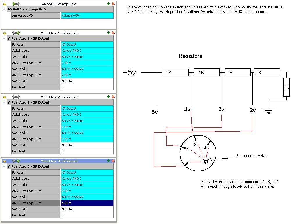
No problem at all. Glad the table thing is sorted for you... On to the DI vs. ANvolt idea  I have attached a picture which will give an example of the idea... Excuse my crappy 'paint' skills LOL
http://i903.photobucket.com/albums/ac236/linkelectro/examplevoltagedividerswitch.jpg
I have done it this way to show the possibility for some others that may visit the forums, because many people have asked 'how do I have adjustable boost knob on my dash board'. This is one way to do it, and if you see what I have done here, you will figre your own answer out.
12v directly in to an AN volt channel will not damage anything, so protection is not needed with other components. The resistors in the picture are only to create a voltage devider. I hope my crappy drawing and words make sense
Jurgen
-
Hi Josh.
Felix is right on man. Take the switching point well out of the way of the highest inj DC you see at startup to test this (eg 50% or higher). This will prove the point quick smart and you know what you're dealing with. Then I suppose chose your switch point from there once the issue is confirmed.
Jurgen
-
Fagadar.
It sounds like you were not connected to the ECU during the process of enabling this table when turning the feature on? The ECU must be talking to PC link when trying to activate, because it doesn't know how many tables are actually still available. When allocating the table/turning the feature on, PCLink wants to ask the ECU 'what tables are left?'. Can you confirm this was or wasn't the case?
The tables available are the same in all Link products. 12 tables are availab;e for all of the fetaures that exist, so I would imagine you have a few left at least. You are loosing me on the Virtual AUX idea however, can you explain what you are trying to achieve with this?
Jurgen
-
Hi Matt.
This is not something I was aware of, but it does come across as sound info what Felix is saying ^^.
Jurgen
-
Legend alright! Good idea Felix!
-
Hmmm.
Thanks Josh
-
Hi Nick.
The Bosche type 'IATB' sensor bough from Link will do the job nicely. That is an open element number, and has a pre-configured CAL in the PCLink software. Just makes things really easy.
Sounds like Felix might know a thing or 2 about the old 3S too
Jurgen
-
Hi Felix.
The injector firing order, will follow ignition firing order, regardless.
Jurgen
-
Hi Quentin.
You are looking for an output from the TPS of 0-5v, so I assume that would be "fuul range".
Jurgen
-
Cool, thanks Grant. Sometimes the other thing that can happen with anything that tries to allocate a table (in fact always) is if you are OFFLINE, it can't see the available tables and will not set it up correctly, such as 'tables won't appear'
Just another one that can catch some people.Jurgen
-
Hi Matt.
Yes that will definately be it... Good work.
PS. OEM runs the pump through a relay, and if you have changed that to run it directly, expect your unit to come in for a repair soon when you pop the fuel pump AUX drive. My advice, run it through a relay ASAP if it is not already.
Jurgen
-
Hi Nick.
Sounds like you're pretty organised. The OEM MAP sensor should be fine to use in this instance, from what I understand they will read up to about 18psi (not confirmed but pretty sure). If you do not have a wide band already, you will not need one as such. Nice to have as a tuning tool (but your tuner will use one anyway).
If you have an AFR gauge you're trying to run, or want to run the closed loop lambda feature it will be nessesary, however if you already have one I wouldn't bother replacing it. They usually work, or dont... So it will be quite clear if it ain't happening for you. They do need callibrating every so often though.
As for a base map, we don't have a ST185 one, however if you use the 205 one it will be pretty close as a start up map with a tweak on the master fuel number (preferably using your wide band). Don't forget the base map will be set up for a plug in so you will have to manually set up your I/Os so to speak.
The only other thing I woud highly recommend is an IAT sensor. This is very important when it comes to fuel trims, especially on a boosted application. It would install as close as practically possible to the throttle plate, on the atmosphere side, to get the most accurate representation of the air temperature the engine is actually eating.
Jurgen
-
That would be great Josh! Do that if you don't mind and let us know... The more info we have the better. Send us your file as well, and we'll make sure there is nothing funny happening in there while we're at it.
Jurgen
speed sensative steering and extreme
in Link G4
Posted
Mike.
Stevieturbo is on to it. You would set up firstly a DI as a speed input, and then an AUX as a GP PWM. Make it a single row table with the axis set up as speed. The numbers that go in the table will be the PWM duty cycle... this is a pulse width, NOT frequency, and that you will have wired off to the steering set up if...
1. It works on pulse width
2. You know the cal, or are prepared to figure it out
Jurgen