


Hussain-vtec
-
Posts
39 -
Joined
-
Last visited
Content Type
Profiles
Forums
Events
Gallery
Blogs
Posts posted by Hussain-vtec
-
-
If you try it please share your results along with engine and set up let see how many of you have benif of this thread explaining l.
-
Hello everyone
I will talk about rpm limit and I will keep it as simple as it gets,
1-Rpm limit mode either ignition or fuel cut this is the main aim you want the limit mode.
2-Turn advanced mode on.
3-hard limit you can turn it on if you want bang fire and action, or less action turn it of and keep hard limit activation on 50rpm only, if on hard limit 200rpm or even 300rpm for large bang and fire action.
4-(end cut) I put a green line in image where my end limit shows 95% off cut.
5-(start cut tp100) I put a pink line in image when it staring a cut where I kept it in 40%
So between pink and green is how fast your cut or how slow it is example (tp low 100) if I rais it to 80% A very fast cut I will end up with if I keep lower number like 30% It will bee slower cut.
6-If you want to do this just put your
(start cut tp low) above
(start cut tp 100) I put mine to(100%) in image
Tp low to( 0.0%) tp to ignore the lower cut tp then re adjust it where you want the lower to be.7-exis decay rate the period of of cut after full throttle is depresd I mark it in orange from 50 to 80 is the good spot if hard limit on and above 200rpm cut range its different from engine to another engines.
for examplee
Exis decay rate is at (5%) and let's say your engine rives 8000 rpm it will drop between shifts to 3000rpm or lower because the period is very long for the cut, but if exis decay rate (80%) rpm between shifting will drop to 7200rpm for example.
8- ignition limit trim is the amount of timing pulling during the limit cut.Here is the image below to explain more
⬇️⬇️⬇️
-
Hello guys,
I wanted to know if I can use this strain gauge sensor on the shifter stick, my gear is h pattern.
and dose it work with the ecu Honda PNP 92-95 & How to wire it.
Advantages compared to other strain gauges:
1 Taobao only metal material of the full bridge strain gauge, excellent heat dissipation, to maximize the elimination of resistance to heat caused by noise, strain resistance 250 ohm
2 high mechanical strength, material for metal (steel + copper coating), can be repeated fatigue test, bending limit far more than ordinary full bridge strain gauge
. easy installation, strain gauge with two screw holes, second strain gauge on the back of the mirror surface smooth degree is high, the workpiece and the fit is very good, & rdquo; good brothers & ldquo; (302 glue), 502 glue easily bubble free adhesive on the workpiece
4. Good sealing, sealing common strain gauge after the installation needs such as polyoxyethylene, in case of full bridge copper wire Kang moisture and oxidation; and this strain gauge has covered the protection of a layer of black layer, so there is no need to to seal
5. Convenient wiring, electric connecting line for standard, red is connected with a power supply (excitation source +), black connection to (the excitation source), green + output, white for output; (strain gauge with shielded wire core without); the wiring is the top of the Mogami Yw-1scThis wire strain gauge.
Thanks in advance

-
On 2/13/2018 at 10:37 AM, Adamw said:
Your wiring is incorrect. Cam signal should go to pin B12. Crank signal should go to B16.
 fainaly it works thanks guys.

-
On 1/30/2018 at 10:31 PM, ClintBHP said:
How i know if Cam signal should go to pin B12. Crank signal should go to B16. And the pin out diagram is blank as showing bellow.

-
4 hours ago, cj said:
try turning off pull-up for both triggers. both are pegged at 4V output the whole time.
I did that still no rpm signal .
-
On 1/22/2018 at 12:26 PM, Adamw said:
The linked sensor is a Cherry/ZF GS1005. The datasheet is here: http://switches-sensors.zf.com/us/wp-content/uploads/sites/7/2012/05/Datasheet_GS1005-GS1007_EN_29_11_17.pdf
For best results use the recommended minimum tooth size from the datasheet:

I suggest 12 teeth as a good balance between resolution and speed capability. Wheel speed inputs must go to DI 1-8. There is a calibration number in the software to adjust for number of teeth and tyre diameter.
You will not need shielded wire for hall type sensors when used for wheel speed.
thanks
-
On 2/8/2018 at 11:38 AM, ClintBHP said:
Nice
")
Thanks brother I tried starting it today, with the same setting above but its not reading trigger what do you think the issue is it the trigger setting?
Please help
thanks
-
Ready to rock


-
On 1/30/2018 at 10:31 PM, ClintBHP said:
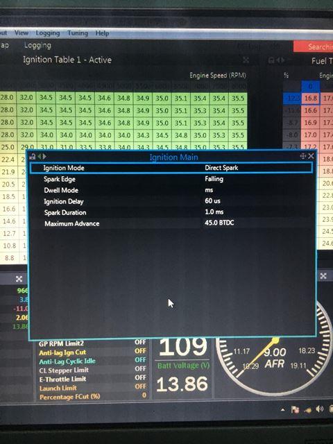
It is important that you make sure you set the following parameters before you turn the ignition on:
Ignition Main -
Ignition Mode = Direct Spark
Spark Edge = Falling Edge
I have included the pinout which you can find in the help file in PCLink and the Dwell settings I run with K20 coils.
Thanks brother here is the wiring diagram
and pc link shots


-
Hi guys.
I have aG4+ PNP in my h22a engine with Oem Distributor installed and wanted to know,
Is the Civic Base Map 92-95 that is already exist in Link Software have the right and correct Dwell time setting Or Not?
If I want to replace my OEM Distributor with a OEM K20 coil on plug and AEM 30-3255 Honda EPM Trigger shall I change the Dwell time setting or keep it the same.
And how to Wire it to the ECU Pin Out Diagram for Coils and EPM And Screen shot of the link software setting please.
See the image attached and don't bother the ECU it will be link G4+
the Link to see the wiring of the AEM 30-3255 Honda EPM Trigger
See the linkhttp://www.aemelectronics.com/files/instructions/30-2860 Coil-On-Plug COP Conversion Kit.pdf in AEM PDF For C.O.P
Thanks
-
Yes it was running just fine and I adjusted the lambda and the master fuel and it’s readable befor on Wednesday just last night start the car then noticed the sound its not running perfect due to non burrning rich a/f mixtures the spark plug is flooded see the image.
Is the inj Timing is correct @430BTDC ?
i clean them and tomorrow will run it again and see what happens
cheers mate


-
I have it tuned with oem neptune ecu bord and i dont have any fuel issues and at made 500+ whp.
Thanks any way
-
i did another cold start with the wide band operating right now here is the map again and log file,
i really don understand what goes wrong before every things run fine but i remove the battery terminal and today i run it and fuel flooded, before one year i have same problem that is why i tune it with other oem ecu, i don have any problems with fuel components,
check this log again if nothing wrong let me know
thanks
https://www.dropbox.com/s/a69jjnkclh0kxl6/cold start Log 2018-01-26 2%3B14%3B46 am.llg?dl=0
-
-
i have a file but not in cold start after it gets warm but the file size is over size this massage pops
You are only allowed to upload 20.48kb.give me your email
-
Guys please help cold start engine get totally fuel folded any suggestion take a look at the setting
last time every thing are mint same base map.
thanks
-
Its running mint thanks guys
-
Dear Link Experts
I have a civic 92 plug in G4+ on My car and I am willing to install rear traction control using Hall Sensor I will buy this one
https://www.diyautotune.com/product/hall-effect-threaded-body-crankshaft-position-sensor/
PACKAGE INCLUDES INLINE RESISTOR PILLS FOR A 5v OR 12v APPLICATION.
Red anodized aluminum hall effect crankshaft or camshaft position sensor. Threads are M12 and mounting nuts are included. Runs off 5 to 24 volts, and gives a nice square wave so there’s no variable voltage issues. Has a 1 meter long, 3 wire pigtail. Here’s what the wires do:
Brown – Supply voltage; connect to either VREF for 5 volt operation or 12 volt switched power.
Black – Output signal. On a MegaSquirt, connects to pin 24. We just set our MegaSquirt up for the VR conditioner and it works great. V3.0 MicroSquirts can also do this, but older MicroSquirts will need to use the Hall effect input. Note that this one requires a pull up resistor. This tees into both the supply voltage and the output signal wire. Use a 1K resistor (now included with the package) when powering it with 5 volts or a 2.4K resistor when powering it with 12 volts.
Blue – Ground.
Be careful if you are switching to this from a previous version of our sensor. The wire colors do not match, and this version requires a pull up resistor.
Specifications
Operating voltage: 5 to 24 volts
Maximum overvoltage and reverse voltage: +30 to -24 volts
Maximum supply current required: 6 mA
Maximum output current sinking: 20 mA
Output type: Open collector
Maximum frequency: 15 kHz
Temperature range: -40 to +125 degrees C
Nominal air gap: 1.5 mm
Thread pitch: M12 x 1 mm
Overall length: 65.5 mm, not including wires
Package material: Aluminum
Sensor orientiation: Not directional
Recommended tooth size is a rectangle measuring at least 2.5 mm x 6.35 mm, with a 5.0 mm tooth height.
The car is vintage so no trigger wheels exist and OE parts to swap in are not available,
so what type of steel trigger wheels I can create and suggested by you guys How many tooth steel trigger wheels is good and reliable?
are there other important minimum/ maximum dimensions ?
This is so I can get the right spec created by CNC
And how to wire it? shall I use shielded signal wire ?
and witch Digital inputs to process and whether the software can be configured for variations in tooth counts?
If not guide me the Right setting.
Thank you
Hussain
-
On 1/20/2018 at 7:36 PM, ClintBHP said:
As Adam mentioned your fuel is all over the place the Master fuel is way too low, I would put 16 in the master fuel and divide the fuel table by 4 as a start.
I will do your suggestion i will increase it to 16 and divide the fuel table by 4 for a strat, this traditional base map hase been made to see where my problem from that’s why i made it, and to be ones i love the ve mode but i though the charge temp correction table is the reason for this problem because after the engine get warm its misfire, what’s about the first start fuel tables like first cranking post startups cold start shall I change them after changeing the master fuel?
-
37 minutes ago, Adamw said:
As well as Clint's advice above, before doing the trigger cal you should first move the distributor to the mid position of its slot adjustment, this normally ensures rotor phasing is most correct (assuming cam timing is correct).
Here is the trigger scope log, i will do that guys again will set the timing with the timing light thanks.
-
6 hours ago, Adamw said:
Can you do a triggerscope at idle and attach here.
You master fuel is very low, what size injectors and what fuel?
It appears you havent adjusted the trigger offset from our base map, have you confirmed base timing is correct?
I dont know the H22a ignition system well, google seems to show the coil is inside the distributor and it has a separate external ignitor - can you confirm?
Regarding trigger offset left the same not toch only I adjust the base timing.
Find this in haltech regarding h22 triggers offset see the link shall you help me in the setting and should i change it?
-
I will do a triggerscope , yes its low but on a mollded base map with every data entered correct have same issue misfire all around entire base map, fuel is 98 octane pump gas, base timing checked and entered by a timing light, h22 distributor is same as b16a angine as you mentioned in google, and the coil is internal in side the distributor.
Here's Mine SpeJDM H22a
-CP 8:5.1 87mm Pistons
-Walbro 450 lph fuel pump
-Fuel LAB FPR set on 50psi
-id 1000cc Injectors
-GM 3-Bar Map Sensor
-All-techwire mill spec rychemed made by me
-
Hello all,I have Link g4+ Plug-in ecu for honda civic obd1 (92-95), i tried tune the car with both modeled and traditional base file, i got a miss fire at idle with both maps.i looked into all correction tables for any strange numbers causing this but all looks fine.attached is both the calibration file, datalog and a short video.My car was tuned with oem ecu on neptune and it was running just fine with no missfire.regards,


G4X BMW E36 M50B25TU Base Map
in G4x
Posted
Hi there sir, just received mine today all ok any notes to give b
efore i install.