Miguel Silva
-
Posts
43 -
Joined
-
Last visited
-
Days Won
1
Content Type
Profiles
Forums
Events
Gallery
Blogs
Everything posted by Miguel Silva
-
Nissan 300ZX G4+ Thunder New IGN Cal 9.pclr RPM Filter3.llg RPM Filter2.llg RPM Filter1.llg
-
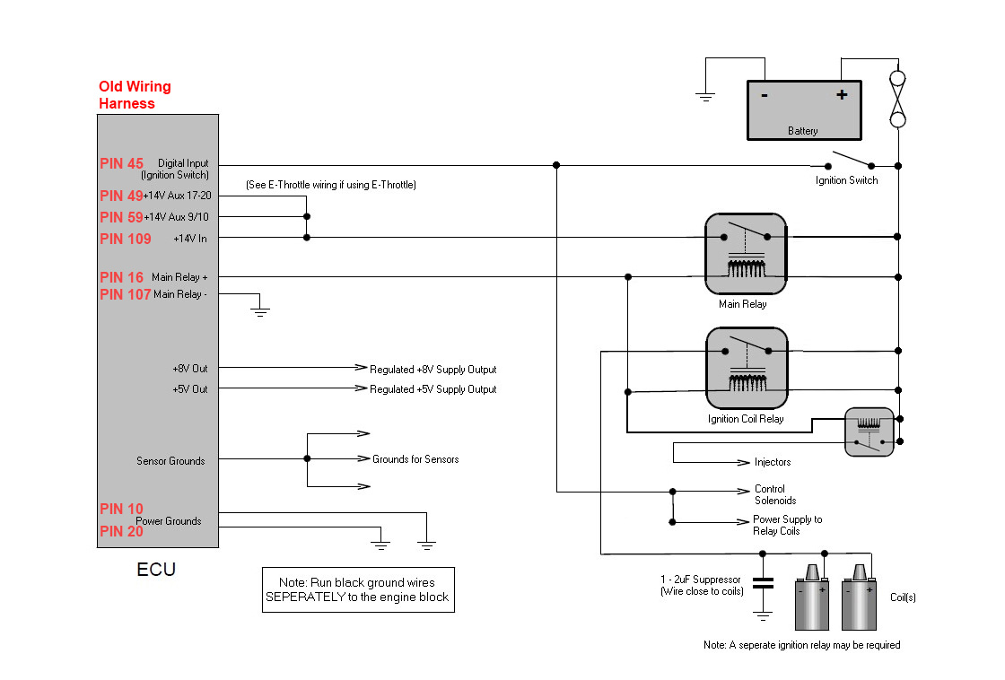
Hi to all, I'm looking for the 2µF Suppressor to wire close to the coils but I'm not certain of what kind can or should be! Can it be like this? https://pt.rs-online.com/web/p/condensadores-de-aluminio/1085440/ Or can it be like this? https://pt.rs-online.com/web/p/condensadores-de-pelicula-de-polipropileno/3887664/ Ho, and to put some perspective as to why I'm looking for a suppressor, I'm having some misfires on my Z32 has I increase boost above 5 000RPMs, and the logged RPMs are a bit unstable unless I apply max filter (even with max filter I get repeating RPMs on log, ex: ... 5 000, 5 050, 5 050, 5 050, 5 200...), also the voltage on the trigger scope drops from 4.1v at idle to 2.3v at 5 000RPM also visible on the log some times teeth aren't registering well but it doesn't report trigger errors. I've re-gaped spark plugs (no difference). I've replaced the stock coils with new Audi R8 more powerful coils (no difference). I've increased and decreased dwell time (no difference). On the most extreme case, if I insist on accelerator pedal to the floor when its misfiring it completely shuts down ignition and whets the spark plugs for a 4 to 10 seconds the car is all rough and and doesn't ignite well, after a few moments it's ok again. It's a scary sensation as it feels as the engine blew up! Any help and suggestions! Very much appreciated. Thanks in advance. Trigger Scope Log 2017-11-8 7;40;24 pm.llg Trigger Scope Log 2018-10-3 7;27;28 pm.llg
-
No I don't, I will just measure a stock one and have it laser or water cut.
-
Tanks to every one, I'm going to opt for a 24-1 or a 50% open and 50% closed CAS disk and forget the stock CAS pattern.
-
(reliable) A good explanation of a NISSAN RB CAS problem that might apply to the Z32 CAS: https://youtu.be/_sEDuNGnRKA?t=4s (not reliable but the same explanation and conclusion) http://www.gtr.co.uk/forum/266505-crank-trigger-upgrade-yes-no.html Post: 27th May 2014, 10:29 PM Asim R32GTR
-
The problems that I have and some others also have are the RPM reading go a bit crazy, as an example on a ramp-run the RPMs should always climb (5400, 5450, 5500...) and on logs I see (5400, 5370, 5370, 5500...) and with the timing light there is always some drift +-2 or 3º from meed to higher RPMs. Applying max filter makes it a little bit better. Has I've posted before it's a belt slop and or some other CAM related harmonics, I'll look for a better explanation from possibly a reliable source and post it here.
-
For the CAS disk there are 2 option 50% open 50% closed and one with a small slot, are they both a real option or just the the small slot will be possible to manually configure?
-
Hi, I'd like to know if it's possible to configure an hybrid CAM/CRANK trigger or if it as to be "hard coded" like the "NISSAN 360 Opto" option? I'd like to use the reset based on NISSAN 360 Opto (0º, 180º, 360º, 540º), that I already have installed on the CAM, and a 60 teeth wheel placed on the crank (one tooth is equivalent to 6º crank revolution). To my understanding and I might be wrong, the NISSAN cam trigger has 2 portions the resets with 4 slots one big that corresponds to 30º or 15 slots, the next corresponds to 22º or 11 slots, next 12º or 6 slots, and finally the smallest corresponds to 6º or 3 slots, and with this setup NISSAN doesn't need more than 1/4!? of a revolution to know where it is exactly (knowing that for each of the reset positions pulses it sees 15, 11, 6 or 3 pulses corresponding to the 0º, 180º, 360º, 540º angle position). The second portion are 360 slots corresponding to 2º, the part that is troublesome because of belt slop and or some other CAM related harmonics and it start to have erratic readings on higher RPMs even applying the highest filter possible. The change I need is to have the reset slots pulses correspond to different angle pulses (0º correspond to 5 pulses), (180º correspond to 3 pulses), (360º correspond to 2 pulses), (540º correspond to 1 pulse) of the crank wheel. I don't know how well explained this is, but hopefully someone understands where I'm getting with this. Setup: LINK G4+ THUNTHER on a NISSAN 300ZX Thanks for the help.

-
Yes, I did but I'm out for a couple of days with no accesses to the car, I didn't try yet. What you have is ROKET not a car you've got gaziillion things going on there. One more thing I'm going to try is to remove the fuse that feeds power to the sensor and see the reaction, this way the only power coming in is on the "main relay+" and the "Ign Sw", if this finally makes it work I just have to add a relay to that part of the circuit. About the ".3 of a volt lower than AUX 9/10 and AUX 17-20 even tho the the voltage in the ECU was the same on all 3 wires" mine does that too, Some thing that bugged me but I was going to confirm what rely goes in the PINS and what is red by the ECU. Again thanks allot for the help.
-
No, this was just configured to test if the ECU sent the command to ground (in this case PIN 16 and plug it to IGN 8 "Plug B - PIN 10" but as I posted above it didn't work configured to ECU Hold Power but it does work as "GP Output" "Condition 1 ONLY" "DI Value 7 = ON" and cycled the state of DI 7 to ON and OFF and the relay opened and closed as expected. Burned it to the ECU and cycled the Ignition key a couple of times and the relay always come alive with key ON. But this isn't a Hold Power function as I don't have the option to hold the relay closed after key off. But on "G4+ 300ZX Thunder very basic.pclr" file the DI 7 is blank and it doesn't work. And that is the base for the post.
-
I'll remove the Ignition Relay and the Injector Relay, It will break the circuit so same effect right!? And test it.
-
I did the new wire and connect it to a new and good chassis ground and to "Plug C - PIN 8(Main Relay -)" and, more of the same, relays don't close. Next I used PIN 16 and plug it to IGN 8 "Plug B - PIN 10" and configured it as an ECU Hold Power output, PIN 45 plug it to DI 7 "Plug B - PIN 30" and configured it as an Ignition Switch, burned it to the ECU, cycled the key ON and OFF and it didn't close the relays also. Next configured IGN 8 output to "test on" "polarity low" and as expected the relay closed juts like when grounding PIN 16. I then configured IGN 8 to "GP Output" "Condition 1 ONLY" "DI Value 7 = ON" and cycled the state of DI 7 to ON and OFF and the relay opened and closed as expected. Burned it to the ECU and cycled the Ignition key a couple of times and the relay always come alive with key ON. So I wold say wiring and relays aren't to blame. Every time I try to use the Hold Power option, I can't make it work. I'm probably not configuring something right and need help troubleshooting this. It can work like this, but i lose the Hold Power option. I've attached the .pclr file from the last configuration with the GP Output. G4+ 300ZX Thunder IN OUT config GP on main relay.pclr
-
I'll make a new wire and connect it to a new and good chassis ground and to "Plug C - PIN 8(Main Relay -)" and test it.
-
If I manually ground PIN 16 the relays close and I get battery voltage minus 0.5V on all +14V inputs, it's a bit of a drop but it's okayish!! If I disconnect PIN 16 "Plug C PIN 1(Main Relay +)" and PIN 107 "Plug C PIN 8(Main Relay -)" and join them together the relays close and the same as above so PIN 107 has ground. PIN 45 "Plug C PIN 2(Ign Sw)" is active when key ON, see image below, and is configured as (active high). When all this PINS are connected back to the ECU, I've tried All 3 options, OFF, Test (ON) and ECU Hold Power and the relays don't change state, they are always open. I'm using Firmware 5.6.4.3240 and the PCLink G4+ EN-JP V5.6.4.3229 software. I've also attached .pclr that I'm using. G4+ 300ZX Thunder very basic.pclr

-
I think I already tried it and no change, but just to be certain I'll do it again in case the test I've done was on a different context!
-
But if the main relay isn't closing why is the ECU powering up on key on and powering down on key off? Can it be from back feed of the control solenoids that's getting power direct from ignition switch without a relay, tricking the ECU to have power? The hold power doesn't have many options: Digital input - (high or low) I have it on high Main relay driver - (off, test on, ecu hold power) I have it on ecu hold power ECU hold power - (time, kill until stalled-yes/no) I have it on 10s and Yes
-
PIN 16, I'l try it, and see if it beavers differently. Well PINS 107, 108 and 116 all share the same ground on the stock harness, and is used by the PTU and Ignition coils, and ends on body and engine grounds. And again on the NISTUNE ECU (it's the stock ECU with a real time programmable ROM) the ignition works fine.
-
Hi to all, I'm having some trouble with the relay controlled by the THUNDER ECU on my NISSAN 300ZX, they just don't pass enough voltage when they are switched on, battery is at 12.5v and the voltage output after the relays is +-10.5v. The ECU powers up but the injectors don't have enough juice to click at 10v and the ignition also doesn't power up to use a timing light. To my understanding relays just have 2 states ON or OFF. I had to do a modification to the original wiring harness as injector had battery power all the time and created a feedback on the THUNDER, so I installed a relay to the injector circuit as can be seen on the attached images red circuit inside the pink area (pink area is based on the Thunder Hold Power Low Side Wiring that I altered to suit the stock harness). When I use this same circuit on a NISTUNE ECU this modification is completely transparent and the voltage out of the relays is the same as battery give or take 0.02V and car runs perfectly, so the relays are not to blame. If I manually bypass the relays the THUNDER ECU sees 12.0V and I can perform injector tests on the software. So can the THUNDER pull a better ground to make the relays close better? I'm using a patch loom made from the A and B Loom Part # 5LB and # 0LA. Should I try a thicker wire for the "main relay+" and "main relay-" ? See attached images and thanks in advance for any help. Miguel Silva .