


BuckinghamIO
-
Posts
24 -
Joined
-
Last visited
Content Type
Profiles
Forums
Events
Gallery
Blogs
Posts posted by BuckinghamIO
-
-
24 minutes ago, Adamw said:
Hang on, what are you doing? The THW pin is the multiplex coms. You will fry the controller sending 12V in there. Does the coolant temp gauge on your dash work? If it does then the multiplex is working and the AC unit should need nothing else.
Are you using the JZX plugin?
My coolant temp gauge has always worked no issues ever, but my AC has never turned on until today when testing.
I'm using a G4X Xtreme but I also had the same issue with the Kurofune.
After some research I can see the JZX plugin ecu sends a low frequency signal to that THW pin which I've confirmed with David via email support earlier today.
Since the G4X can do 1hz it was suggested I try to emulate what the JZX plug-in ecu does via a PWM output, which seems to work via test mode and now my button actually activates the DI where as before it never did.
-
Update: Using an Aux output to send a PWM 1hz signal to the THW pin on the climate control seems to work, I'm going to confirm this tomorrow with a few more tests though.
-
31 minutes ago, essb00 said:
Turn on the DI 1 Pull-up resistor
Just to add I've tried it with both on and off
-
I can see that on the plugin JZX ecu CAN 2 is used to send data to THW pin so I'm guessing that is what I need to do but I'm unsure how wiring wise...
Which side of CAN 2 H/L goes to the pin and where would I connect the remaining side?
1 minute ago, essb00 said:Turn on the DI 1 Pull-up resistor
That does nothing, there is more at play here it seems, the JZX100 plugin in ecu confirms this:
QUOTE from plugin ecu:
CAN 2 on the JZX100 is used to transmit the ECT value to the temperature gauge in the vehicles dash and this value is also used by the AC system. When first receiving your G4X JZX100 ECU the CAN 2 will be set up already but should something change and you need to restore the CAN 2 setup to original, complete the following steps:
-
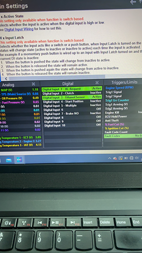
Im starting to finalise all the wiring ready for my second mapping day and I still can't seem to get AC request DI input working correctly.
We had the same issue even on the older Kurofune. I've taken the settings from the JZX100 default map for G4X which confirms:
DI 1 (My AC request) goes LOW
AUX 4 (AC Clutch) goes LOW
I have these settings saved and applied however this makes my AC request input stay active all the time regardless of whether my AC button is pressed or not.
I've confirm the correct pin is being used and I've attached picture below along with a picture of my settings.
If the pull up off the DI is constantly active with the pull up off its not active but I also can't make it activate with the button still
UPDATE: I've been made aware that maybe we need to supply THWO data for the A/C to work properly? is it possible to do this with a wire in ecu or does the JZX100 plugin have a specific hardware change to accomodate?

-
-
Usually the ECU that controls the TRC/ECTS fails anyways (capacitors).
I would just unplug the connection from the throttle body, I believe it's the one closest to the radiator... and then just remove the bulbs from the cluster as they just pop out.
-
13 minutes ago, Vaughan said:
Yup, we tried to make the offsets closer to 0 for vehicle specific modes in G4X
Ahh right makes sense however this is a wire in version rather than a plug an play? Any difference here?
-
6 minutes ago, Vaughan said:
Have you checked your ignition timing? I would expect your trigger offset to be near 0 on a G4X.
I put it the same as what was on the G4+ which off the top of my head is something like 205? has something changed in the G4X to make this drastically different?
-
Hi,
I've recently purchased a G4X Xtreme to replace my older Kurofune, everything has been wired in and checked over along with the map being manually transferred to the G4X platform.
The car wont start currently but seems to have good trigger signal, RPM signal and the issue seems to be isolated to spark as the injectors are working it seems.
Would anyone be able to check over a few of these logs below and maybe point me in a direction of how I can get the car finally started, I'm worried I may have missed something during the G4+ > G4X map transfer as some options were different.
I have attached 2 trigger scopes, 2 pc log files and the map file in the dropbox link below as the forum wouldn't let me upload them due to file size:
https://www.dropbox.com/sh/ztt3dwhq56wfeh9/AAD39fSeKn2bMOv7Z7Lergz0a?dl=0
-
Selling my Link Kurofune if anyone is interested £900
Car was mapped yesterday making 503hp on a Toyota Chaser JZX100 but I'm looking to add EGT, DBW and traction control so will be upgrading the a Link Thunder now instead to make life easier.
I can supply the plug and play loom needed to fit a Toyota chaser if needed for £50.
-
3 hours ago, Mike2J said:
I had similar spikes on a 2JZGE VVTI with BC272 cams using Kurofune. Had to mess around with trigger two arming thresholds a lot to get the system happy and not spike. Required much more arming voltage than other 2JZ's Ive done. Unsure if its down to the ECU or the engine combo.
Looking at your latest map you have your VVTI cam control mode set to Off, and in the logs the ECU is not able to track Inlet cam position. This could be contributing towards your sync errors. Haven't ever tried running a VVTI with cam control compeltely off, normally if I want to diagnose VVT system I just set RPM lockout very high. ECU still tracks inlet position like this which is helpful in diagnostics. If your VVT solenoid has no duty then the cam gear can bounce, especially on idle and free revving.
The car in with the tuners at the moment and the map posted here is out of date.
Shortly after my last post there was an update from Dave at tech support and we have another possible solution of adding much bigger resistors (25K) to emulate the trigger signal being passed through/shared via the stock ECU which isn't there in this case.
Interesting you say you had to really fine tune the trigger arming like that... It seems this is never a issue normal so much be down to the specific differential trigger hardware system in the kurofune.
Essentially though no matter what you do, when you hit 3,000 rpm, massive rpm spike well over 10,000 no matter what you seem to change.
-
@TechDave I believe you have spoke to Martyn at EngineTuner in regards to my issue with the Kurofune and the trigger issue and gave some insight that a 3k resistor may be needed.
The resistor has been added and Martyn has updated me to say there has been no change, which is really frustrating as I have no idea what we can try next or if I need to just completely replace the ECU as quite a significant cost when this should work...
Any input would be greatly appreciated as I really have no clue what to do now other than to take the car back and run more checks my self.
-
2 minutes ago, Adamw said:
Sorry, I had so many logs open tonight I must have looked at the wrong one.
Your arming threshold is still too high. Why didnt you set them as per my example above?
Ahh my bad, sorry it was a long day on Sunday when putting the whole front of the car back together

-
Even in the normal log? I can see spikes of 10k twice?
-
On 3/13/2020 at 10:02 AM, Adamw said:
Yes, the rpm spike is due to a trigger error. This means the trigger pattern received by the processor didn’t match what it expected to see. Most likely a tooth didn’t meet the arming threshold so it was ignored.
Well on Saturday I finished putting car back together and I did the following:
- Cleaned the crank sensor earth (Where the bolts also secures the sensor)
- Replaced the battery (Much bigger and beefer version also)
- Replaced the spark plugs
The car fired up straight away and seemed to idle without doing the whole up and down RPM rev counter thing and I even gave it a few blips of the throttle to check which all seemed great!
I did take some logs and I can see two instances of a high RPM, could I see a RPM spike on the logs from hitting the 3k limiter? as I know I did that once by accident? @Adamw
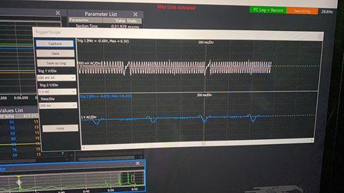
I've attached the latest map file, 2 trigger scopes and the log file.
Trigger Scope Log 2020-03-14 8;19;54 pm.llg Trigger Scope Log 2020-03-14 8;21;23 pm.llg 2 RPM spikes.llg latest map 1jz.pclr
-
22 minutes ago, Adamw said:
Nothing at all. Just found "Day 2 triggerscope 1" is a valid capture but neither of the other two show anything - just 0.1V of noise.
Both cam and crank are only just making 0.3V in that capture though so that is very low. Its almost like there is no ground connected to the sensors or something. Is it a piggy back install?
Try your arming thresholds something like this:

No, the triggerscope can only capture about 720deg.
Okay I'll try those values. Can you confirm you can see the RPM spike in the log though?
It's a standalone install, the cam sensor does make -3v to 3v when running but the crank sensor I think stays a little low.
I've also attached some other trigger scopes from the first day I was logging.
-
8 hours ago, Adamw said:
None of the trigger scopes you have attached have any data but based on those screenshots above I would say the arming thresholds need to be much lower. Set the whole table to about half it’s current values on both trig 1& 2
The VVT trigger modes don’t have the same restrictions in regards to cam tooth position. Yours looks normal for 1J/2J.
No data as in nothing in them at all? I just downloaded them and they showed the trigger scopes fine? If you mean nothing of concern then okay.
We have tried to lower the arming voltages with no effect but tonight I'll fit a new battery, new plugs, clean the crank sensor ground and try again.
Is there any way to log both trigger scope and normal logs so I can overlay them?
-
This post seems to follow a similar issue...
-
2 hours ago, remski2 said:
Your AFR's are 16-19.

Not concerned about fuel as the car did start originally but even when it did start we had engine RPM spikes which then kept activating the RPM limit etc when the car was only idling.
I checked the crank trigger sensor teeth tonight as per @TechDave feed back and all the teeth look fine especially before and after the gap.
Is it purely down to the cam and crank signal over lapping? If so how can I fix that?
Worth noting the car ran fine on the stock ECU prior to the link and new loom too. Not sure how fusssy the stock ecu was with signal
-
3 minutes ago, Brad Burnett said:
First i would put some fresh plugs in it and cut the values in the idle/low load area of the fuel pump by half(all the 77s).
Whats your base fuel pressure set to?
Base pressure is around 43-44psi
I've had some feed back TechDave through my eletrician and according to him I have a potential bent/broken trigger tooth...
It's worth noting the car did start before.
-
@TechDave I believe you have spoke with Chris from Phoenix in regards to the issues I am having? Here is some more information just incase it helps too.
-
Hi,
I recently fitted a Link ECU and after our first start we noticed that the RPM counter in the car and engine speed values on the ECU would spike to very high numbers even just idling. (9k, 15k etc)
I did some troubleshooting using some of the other topics around the forum and checked the following things:
Troubleshooting:
- Checked crank sensor polarity via trigger scope (Correct)
- Checked cam sensor polarity via trigger scope (Correct)
- Checked engine earth resistance (Cylinder head, block, alternator, inlet and chassis to negative battery terminal/Chassis) (.002 ohms so that seems correct)
- Checked Cam sensor resistance (1200 ohms approx which is within spec)
- Checked Crank sensor resistance (1780 ohms approx which is within spec)
- Cleaned the crank sensor
- Adjusted trigger offset values with no improvements
Car information:
- Bosch EV14 850CC injectors (Fully sequential)
- Toyota 1.8 Coils (Full sequential)
- Stock cam sensor
- Stock crank sensor
- Trigger offset 205
I'm very much running out of ideas and now the car wont start as I'm pretty sure we have fouled the plugs where as it did start before but was very erratic.
We know we are getting Trigger errors however when we changed trigger 2 type to Optical/hall these went away but the car still didn't start. I'm putting that down to bad spark plugs which I'll replace with coppers today.
If the trigger errors go away when using optical/hall, I'm guessing that means there is to much overlap between cam/crank signals, but I'm not sure how I solve that? Should I check mechanical timing incase thats the cause?
I've attached a couple Trigger scopes, log files and map file, any help would be very appreciated!
Thanks
Sam
trigger scope day 2 no fuel pump just cranking.llg day 2 log export 1 (fouled plugs).llg 1jz base map.pclr day 2 trigger scope 1 (fouleed plugs).llg log export day 2.csv trigger scope day 2 no fuel pump just cranking attempt 2.llg


1JZGTE Crank but no start
in G4x
Posted
I do the following steps to set base timing:
By bridging the two larger pin connections the car will crank but not start due to the fuel pump being disabled but you can stil use the timing gun to determine if the car is commanding 10 degrees.
On the G4X due to software changes the number will be close to 0, in my case I only need to offset by 5 degrees.
Once the base timing is set save it and exit out of the window, once your done there all future timing changes can be done via the ignition map.