Dave Kriedeman
-
Posts
1,365 -
Joined
-
Last visited
-
Days Won
48
Content Type
Profiles
Forums
Events
Gallery
Blogs
Downloads
Everything posted by Dave Kriedeman
-

Vipec V88. Table for quick throttle close?
Dave Kriedeman replied to 07_wrex's topic in ViPEC V Series
Hi Sean, does your engine have tumble valves?. You have some very complex ignition timing control setups in your PCL file. You have obviously spent a lot of time setting this file up for your engine. Regards Dave. -
Vipec V88. Table for quick throttle close?
Dave Kriedeman replied to 07_wrex's topic in ViPEC V Series
Hi, I forgot to add, when I refer to decal fuel I am referring to the high vacuum load sites in the fuel table. For example if you where coasting down a hill in 4th gear with your foot off the throttle and your engine was running at 40Kpa, you then downshift to 2 nd gear for more engine braking or getting ready to reaccelerate as a passing move on slower traffic. When you down shift to the lower gear you will enter higher vacuum sites of the fuel table that may not be tuned for example 15 Kpa, I realise over run fuel cut is there to help take care of this, but I am trying to point out some other underlining contributing factors. Regards Dave. -
Vipec V88. Table for quick throttle close?
Dave Kriedeman replied to 07_wrex's topic in ViPEC V Series
This is correct and is OK to do, however you must check that the Throttle enrichment settings cant activate during these rpm and tps settings. I prefer to have all of my idle control parameters etc setup correctly to obtain correct idle speed and have the DBW TARGET SET TO 0 at the 0 AXIS. Using the idle ignition timing table can also add to more refinement here. I personally never use idle speed error as an idle ignition timing axis. Regards Dave. -
Vipec V88. Table for quick throttle close?
Dave Kriedeman replied to 07_wrex's topic in ViPEC V Series
Hi, If you have values other than 0 at the 0 axis, you must remember that the throttle blade will be open x amount dependant on your target table versus FPS. Obviously the Throttle blade being open slightly will have an effect on the TPS voltage also, So if you look at your DBW target table from 3000 rpm back to 0 rpm your cell number increases, the ecu will see this as the throttle is opening and therefore if not setup correctly the ECU will add acceleration enrichment as it is seeing the TPS value increase as the rpm reduces. I add 3000 rpm into the equation as from 3000 rpm set at 0 and the next site is 2500 rpm has a value of 1% so the ECU will interpolate between the 2 cells. So a combination of this along with your overrun fuel cut settings may be contributing to your issue. There can be lots of contributing factors, so really you need to log the parameters such as TPS SUB and Main, FPS SUB and Main, Ignition angle, VVT value, engine RPM, AFR, MAP, MGP, etc. The parameters that can or could influence this should be logged and studied. Sometimes when trying to find annoying issues I disable extra fruit (controlling parameters etc) and simplify the setup and slowly creep back up onto my final combination, taking a step at a time and evaluating the impact on the engines behaviour. You have a lot of controlling variables on your engine, which is perfectly fine, however as an example it could be a single simple PID value that is not quite right and create small little niggling characteristics than can be frustrating to yourself the end user. Regards Dave. -
Vipec V88. Table for quick throttle close?
Dave Kriedeman replied to 07_wrex's topic in ViPEC V Series
Yes, it is preferred that your 0 line should be all 0 values. Closed FPS 0% however the engine is idling at at X rpm which will make it run in a different fuel cell area, You should really tune your DBW settings correctly as having values other than 0 can create issues on decel fuel. The Target table shouldn't be used as an idle correction table. Regards Dave. -
Check out this log. Map sensor or boost control issue?
Dave Kriedeman replied to 07_wrex's topic in ViPEC V Series
Hi, looking at your data log, confuses the crap out of me. Confusing me isn't hard but. In the log I see a peak MAP pressure of 740 odd KPA but also looking at your boost PID's seem to be staying low and not responding much at all. You did have 100% TPS at 740 odd Kpa, however when you look at the log it just looks wrong. Surely your not running 93 odd psi of boost. Maybe faulty MAP sensor , or scaled incorrectly or the engine had a huge back fire. Regards Dave.
-
Vipec V88. Table for quick throttle close?
Dave Kriedeman replied to 07_wrex's topic in ViPEC V Series
Hi, may i ask why your DBW target table has the low values in the O% low rpm row, is this to help your idle speed control or something. Also looking at your injector dead time values it would appear you are running around 50 psi fuel pressure. Regards Dave. -
Vipec V88. Table for quick throttle close?
Dave Kriedeman replied to 07_wrex's topic in ViPEC V Series
Hi, have you ever tried turning Overrun Fuel Cut off and tuning the decal fuel. I sometimes do this to tune the high vacuum areas of the fuel able that are never reached. Turn off Overrun fuel cut , find a hill with a nice long down hill gradient. By selecting different gears on decal coasting down the hills you can hit the high vacuum fuel cells and tune them to your target AFR, normal stoich or around 15:1. You can manually tune this with someone else driving or datalog the downhill decent and use TPS or MAP as your trigger, Example active from TPS value < 5 % or MAP <30 Kpa. This way you can go back through your datalog and manually tune these sites. Another thing you can try is to play with is the Ignition Transient Retard settings. Have a play and see how you go. Regards Dave. -
Hi, can you please let me know what maximum boost you wish to run and maximum desired rpm please. Also, you are going to run the engine on E85 but you don't wish to run a flex fuel sensor, just incase. Regards Dave.
-
Hi Rick, Try the following, Go to the OPTIONS TAB in LINK G4+ software, Select connection mode to = MANUAL Connection Port to = The COMM PORT THAT YOU ARE USING SET BAUD RATE =Â 19 200 and click OK. Retry to connect to the G4 +. Let me know how you go. Regards Dave.
-
Hi Bob, So what you are stating is you have a GM 3 BAR map sensor wired to your G4. You have tried connecting it to both analogue volt inputs 4 and 5. But when you go to the OPTIONS TAB at the top of the screen and go down to the 7 th selection MAP SENSOR CALIBRATION, click on this selection it wont calibrate, correct. 99% of the time when I see these errors the customer / installer has not terminated the MAP sensor correctly to the ECU. The ECU will display an out of bounds or error code <5 or 5> than BAP or MAP, I cant quite remember exactly the error message. This error is fairly common as the schematic diagram for GM MAP sensors I have seen come in two different formats. One the pin out will show the example looking down on top of the MAP sensor with the 3 pin allocations and descriptions. The second will come looking from underneath the MAP sensor and it will show the vacuum hose fitting on the right of the MAP sensor which just looks like a circle, This confusion normally leads to the two outer pins being located incorrectly. Swap the 5 volt ref and sensor ground wires over (the two outer wires) and try to recalibrate. I hope this helps. Regards Dave.
-
Hi Shadow, all good, yes if you lift your fuel pressure that will match my injector dead times I have setup for your ID 2000's. regards Dave.
-
Hi mate, I should have your PCL finished later today. I was in a lot of pain yesterday and the pain killers put me to sleep. I also spoke with ASHLEY, LINK- ViPEC engineer regarding your AEM map sensor. It appears we will have to rescale the cal in KPa values not PSI as the background mathematics and processing used by the CPU does not understand the PSI values. It requires MAP and then the ECU can do the conversion back to PSI. I will rescale the cal to KPa and set the rest up for you. Are you using E85 all of the time ? Can you lift your fuel pressure to around 43 psi please. Regards Dave.
-
Well I am glad I asked for your engine specs. Regards Dave.
-
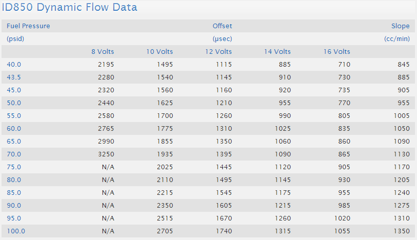
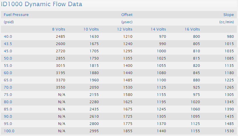
Hi all, It seems that alot of people are using or considering using ID INJECTORS. I decided to post up the following information regarding their deadtimes etc. Hope this is of some help. Regards Dave.


-
Hi all, There seems to be a lot of interest in people using or intending to use ID injectors. I decided to add the following Injector Deadtimes values etc for those who need them. Regards Dave.;


-
Hi mate, too late, I have already started. What fuel pressure are you running, so I can setup the correct dead times. Does your engine have aftermarket camshafts etc. Basically can you list the parts or specs for engine, Turbo stock or bigger, exhaust manifold stock or custom etc, etc. More info the better. Yes I wanted to know what the MAP reading is when the engine is idling, the Y AXIS of the MAIN FUEL TABLE. Your MAIN FUEL table Y axis is setup as MGP PSI so at idle it should read -??? at idle. Regards Dave.
-
Hi Shadow, firstly looking at your data logs etc, you need to setup the properties of anything to do with your MAP sensor as a min and maximum setting. Right click on the data log page or anywhere that the AEM MAP sensor data will be displayed such as a value list etc. You need to set the MAP parameter up as MANUAL not AUTOMATIC. Set your MINIMUM value to - 15 and your MAXIMUM to 60. To change the output reading of a gauge such as LAMBDA to AFR, you need to go to the OPTIONS tab at the top of the page, Go to the UNITS page and you will have METRIC, IMPERIAL or OPTIONS. Select options and in both the Metric and Imperial setup tabs, select AFR instead of Lambda. Or if you press the "U" key on any page it will convert the displays from METRIC to IMPERIAL and vice versa. Also check your Target AFR /Lambda table as you have started it at 2.9 psi positive pressure with target values of14.7 all the way up to 10.2 psi positive pressure. You need to rescale you Y axis back to -ve values also, otherwise your AFR is dangerously lean. I had surgery yesterday and I am in a lot of pain, but I am going to run your PCL up on my i88 and simulator to test the boost gauge setup and outputs etc. As for it running very rich, firstly you need to confirm what manifold vacuum or PSI, MGP, MGP PSI your MAIN FUEL TABLE is running at. What value is the Y axis and how many rpm is the engine idling at. Have you carried out a TPS and MAP sensor calibration and pressed F4 to save these values to the ECU. As for the idle speed, until you get the idle mixtures etc under control I wouldn't bother with that at all. However you can try adjusting the IDLE BASE POSITION TABLE values to start with. I will create PCL file for you to try with your injectors etc setup. Give me some time however, on lots of pain killers so I am a little slow today. Regards Dave.
-
Hi Steve, Well spotted mate, a lot of people wouldn't even notice. The reason we are using Deg C as the basis of our scale as it will allow us to use negative values. At the end of the day it could be chickens we use as it is purely used as a reference to achieve a desired output reading. I will put in a request for this feature to be added, so that INCHS/HG and PSI or just -ve PSI (vacuum) and +ve (boost) pressure can be chosen. Regards Dave.
-
Hi Shadow, Sorry I just realised you are using a 5 BAR MAP sensor. I only used the 1 BAR sensor specs, sorry. So your MAP sensor should be P/No 30-2130-75. What you have done is correct. I have added the properties for the Dial gauge so you can read the vacuum as well. Your guesstimated voltages on your cal are a little different than mine in some areas however, either set will put you in the ballpark. If you use a mechanical gauge and open the runtime values list F12 and monitor the MAP voltage at the mechanical gauge readings of boost and vacuum, you will be able to build a lot more accurate cal file scaling. But try using each of the Cal files we have created, obviously one at a time and see how accurate each is compared to a mechanical gauge. Regards Dave.

-
Hi Rick, No, it should be seen as a USB device. Do you have your PC lead plugged into the USB PORT or the CAN/SERIAL port on the ECU. It must be connected to the USB port on the ECU. Regards Dave.
-
Hi, depends on how much boost you wish to run. I will set the example up for 15 psi boost. In my examples are using a straight CAL 4 and also a cal table 1 which can produce a more linear curve to match your sensor. However some of the voltages are guesstimated to match the pressure value, some of the values can not be exactly replicated in the cal 1. However if you spend the time you will end up with a much more accurate MAP value. Regards Dave.

-
Hi Bob, Sorry, I cant delete my previous post. I have just read what I have written and my response is incorrect. Sorry it is my very potent medication I am on. I believe you wish to use PSI as your Y AXIS to set boost,  On the G4+ platform you can. On the earlier platform you can only use, Kpa, MGP, MGP PSI (PSI), TPS ETC. Regards Dave.
-
Hi Shadow, set your MAP sensor up as per my screen shot, however you will have to scale your 0-5 volt outputs to represent the vacuum and positive pressure as I don't know what they are. This should work. Ignore the Digital guage reading as it was already reading 85 Kpa in the base map I used for this demo. Regards Dave.

-
Hi Rick, What OS are you using, windows 7,8 XP etc. Have you read the communications help file thoroughly in the HELP file, 99% of the time the answer is in the Help File. Regards Dave.