


djhedges
-
Posts
17 -
Joined
-
Last visited
-
Days Won
2
Content Type
Profiles
Forums
Events
Gallery
Blogs
Downloads
Posts posted by djhedges
-
-
I have a Razor PDM & Fury ECU talking over CAN bus and controlling things like the fans & fuel pump correctly. My next goal was to actuate the brake lights with the PDM based on pressure voltages from the ECU.
Wiring currently
- ECU AnVolt 8 - Front brake pressure
- ECU AnVolt 9 - Rear brake pressure
- PDM PWROUT2a - Brake lights
Bonus points for redundancy such that if a brake pressure sensor fails the brake lights still work.
Extra bonus points if we can make the brakes blink.
-
A bit of a follow up. You were correct in that the trigger wheel was bent. After swapping it we now see a better trigger scope and zero error counts.


-
Yes it was connected to a laptop. Although for a while I had an ouput always powering the brake lights which the killswitch would turn off even if a laptop was connected.
-
I attempted to wire the killswitch per the attached diagram but it didn't quite work.
- I ran a wire from the Z terminal to the PDM for the IGN SW pin
- On the other side of the Z terminal I ran a jumper wire to the alternator & starter side of the power
Normally the power to the coils is run on the Z terminal which in the off position is disconnected. I think the car has this killswitch based on the Z & W labels I'm seeing on the back. I'm still confused as to why the car kept running with the killswitch in the off position.
https://www.pegasusautoracing.com/document.asp?DocID=TECH00109(1).png.7b3f089ab63a6359b81649f6ec44ba84.png)
-
I got it to idle on it's own by cranking with the throttle open a bit for a minute or so. I think the header is either cracked or has a hole in it. I've not run these headers before.
I did try a number of things before starting it. Ran a seperate shielded wire for the trigger signal to the ECU, swapped crank position sensors with an older one and I swap out the spark plugs. I didn't snag any logs unfortunately and the trigger scope looks the same.
My next steps are to swap the headers and figure out why the killswitch didn't work. I apologize for the music in the background. I couldn't hear it over the exhaust.
-
ICM 0227100209 https://www.autohausaz.com/pn/4A0905351A (Although the picture looks different but it has 7 pins)
Coil 0221503002 https://www.autohausaz.com/pn/00098
Crank Sensor 0261210107 https://www.autohausaz.com/pn/0261210107 -
I also pulled all the spark plugs last night and cranked the engine. With the timing light set to 10 it lines up with the TDC marks on the crank pulley.
-
I tested fuel pressure before the fuel filter and before the fuel rail. It held >60 psi for 10 minutes after priming the pump in both locations. I also replaced the fuel filter while I'm here.
I then tee'd the fuel pressure gauge inline with the fuel rail and watched it as it was cranking. It stayed in the 55-60 psi range. This was with an additional 50% fueling.I also logged the PDM this time. I'm dubious there's anything useful there.

corrado_20240122_00_50_fuel.pclx PC Datalog - 2024-01-22 6;35;13 pm.llgx Trigger Scope - 2024-01-22 6;35;29 pm.llgx 20240122_00.pdmlog
-
I haven't touched any of the fueling parameters other than experimenting with some of the cold start settings. I did try lowering the trigger 1 arming threshold by 0.1 across the row and tried setting a target idle rpm of 1200 in this last attempt.
PC Datalog - 2024-01-21 9;15;32 am.llgx Trigger Scope - 2024-01-21 9;16;05 am.llgx corrado_20240119_01_idle_rpm_1200_and_isv (1).pclx
-
First time wiring an ECU and I think we're getting close. It's finally cranking and making noises but not quite idling yet. I thought the header had a hole in it at first.
I've tried a number of things- Trigger offset of -84 or 276 (and played with ±10 degrees)
- With a timing light set to 0 the marks on the crank pulley lines up best at 6 degrees BTDC in the calibration settings
- I tried adding +10% fuel on cold start cranking table across the row (@ +20% there's backfires in the exaust)
-
I pulled the spark the plugs and tested the pairs that are firing to ensure that they fire per the firing order 1, 5, 3, 6, 2, 4:
- IGN1 - Clyinders 1&6
- IGN2 - Clyinders 2&5
- IGN3 - Clyinders 3&4
- If I crack the throttle a bit it idles roughly like in the video but on it's own
- Weeks ago I verified the injector wiring with a volt meter before installing the intake manifold
Other things worth mentioning:
- ECT signal is from a linear 0-5v out from an AEM gauage which is reading ~10 degrees higher than the gauge itself. Although I did calibrate it against a chart from AEM. I assume this doesn't matter though.
- The motor has 276 cams, 11.75:1 compression and MS109 fuel
- Link 1.15 bar MAP sensor
- Link LSU 4.9
Tomorrow I plan to check if ever configured the idle stablizer valve. What else should I try?

-
Thanks for the suggestions.
So for the idle valve & purge valve should I ground those to the ECU? If so which pin?
-
I'm getting to build my first wiring harness and would appreciate one more review and a few questions before I get started. Below my current plan for the PDM pins. It's a NA build with 12:1 compression on stock injectors. ECU is a Link Fury.
razor_pdm:ADIO1,link_ecu_a:+14V
razor_pdm:ADIO1,link_ecu_b:+14V Aux9/10
razor_pdm:ADIO2,idle_stablizer_valve:Pos
razor_pdm:ADIO3,vapor_purge_valve:Pos
razor_pdm:ADIO4,LSU4.9:Heater Power
razor_pdm:ADIO5,aux_coolant_pump:Pos # Secondary small electral water pump that had a 5 amp fuse
razor_pdm:ADIO5,transponder:pos
razor_pdm:ADIO6,coolant_temp_gauge:12v
razor_pdm:ADIO6,fuel_pressure_gauge:12v
razor_pdm:ADIO6,link_keypad:+12V
razor_pdm:ADIO6,transmission_temp_gauge:12v
razor_pdm:ADIO7,wiper:high
razor_pdm:ADIO8,wiper:park
razor_pdm:CANH,link_ecu_b:DI10/CAN2H,link_keypad:CAN High
razor_pdm:CANL,link_ecu_b:DI9/CAN2L,link_keypad:CAN Low
razor_pdm:IGNSW,ign_switch:2
razor_pdm:PWROUT1a,fuel_pump:pos # rockauto lists a bump with 8 amps average
razor_pdm:PWROUT1b,coil:Ubatt # <8 amps according to bosch motorsports catalog.
razor_pdm:PWROUT1b,injectors:Pos
razor_pdm:PWROUT2a,brake_lights:pos
razor_pdm:PWROUT2b,brake_lights:pos
razor_pdm:PWROUT3a,starter:solenoid
razor_pdm:PWROUT3b,starter:solenoid
razor_pdm:PWROUT4a,spal_fan_1:pos # 7.6 amps
razor_pdm:PWROUT4b,spal_fan_2:pos #6.3 amps
razor_pdm:neg,battery:neg
razor_pdm:pos,kill_switch:starter- What is the current draw of the Link Fury ECU? I'm hoping a single ADIO pin is enough to suppor the ECU.
- I planned to run the coils, injectors & fuel pump off the same high output. Should I also add individual inline fuses?
- The car had 5v front/rear brake pressure sensors that I was planning to wire to the ECU. Is it silly to drive the brake lights over CAN to the PDM?
-
Gsum = x + y + z accelerometer channels
It can be used to get an idea of much of the available traction a driver is using. Think traction circle.- mapper and castillaricardo
-
 2
2
-
Now that you mention I seem to recall the coolant reservoirs wicking being a possible issue. I'm torn though because having that signal could save an engine. I'd rather redo a harness then have the engine rebuilt. On the plus side race cars get wrenched on so much that hopefully I'll catch it early on.
On 1/3/2023 at 4:43 PM, aerace_fab said:You should highly consider using excel or google sheets to make this diagram.
If you need help i can show you a few examples of how it's done properly.
I'd be happy to take a look at a google sheet example if you have one handy. I could always export what have to now to sheets if needed.
-
Thanks for looking.
I wasn't sure what to connect the two pin low coolant sensor from the VW coolant reservoir. If I recall correctly this is simply two pins submerged in the coolant. If coolant is present it closes the circuit.
I have not seen Scheme-It yet. It's not the prettiest diagrams but I guess I've gotten used to looking at them. I found using graphviz the easiest to maintain so far. It's defined once in https://github.com/djhedges/corrado_wiring/blob/main/corrado_wiring.py by defining nodes and paths. For example.
Node('icm', ['Transistor1ecu', 'Transistor2ecu', 'Transistor3ecu',
'Transistor3coil', 'Gnd', 'Transistor2coil', 'Transistor1coil'])
Node('coil', ['Coil3', 'Coil2', 'Coil1', 'Ubatt'])# Coils
AddPath((
('razor_pdm', 'PWROUT3a'),
('coil', 'Ubatt'),
), 'red')
AddPath((
('icm', 'Gnd'),
('engine_bay_ground', 'Gnd'),
), 'black')
for i in range(1, 4):
AddPathWithMap((
('link_ecu_a', f'Ign{i}'),
('icm', f'Transistor{i}ecu'),
))
AddPath((
('icm', f'Transistor{i}coil'),
('coil', f'Coil{i}'),
), 'white')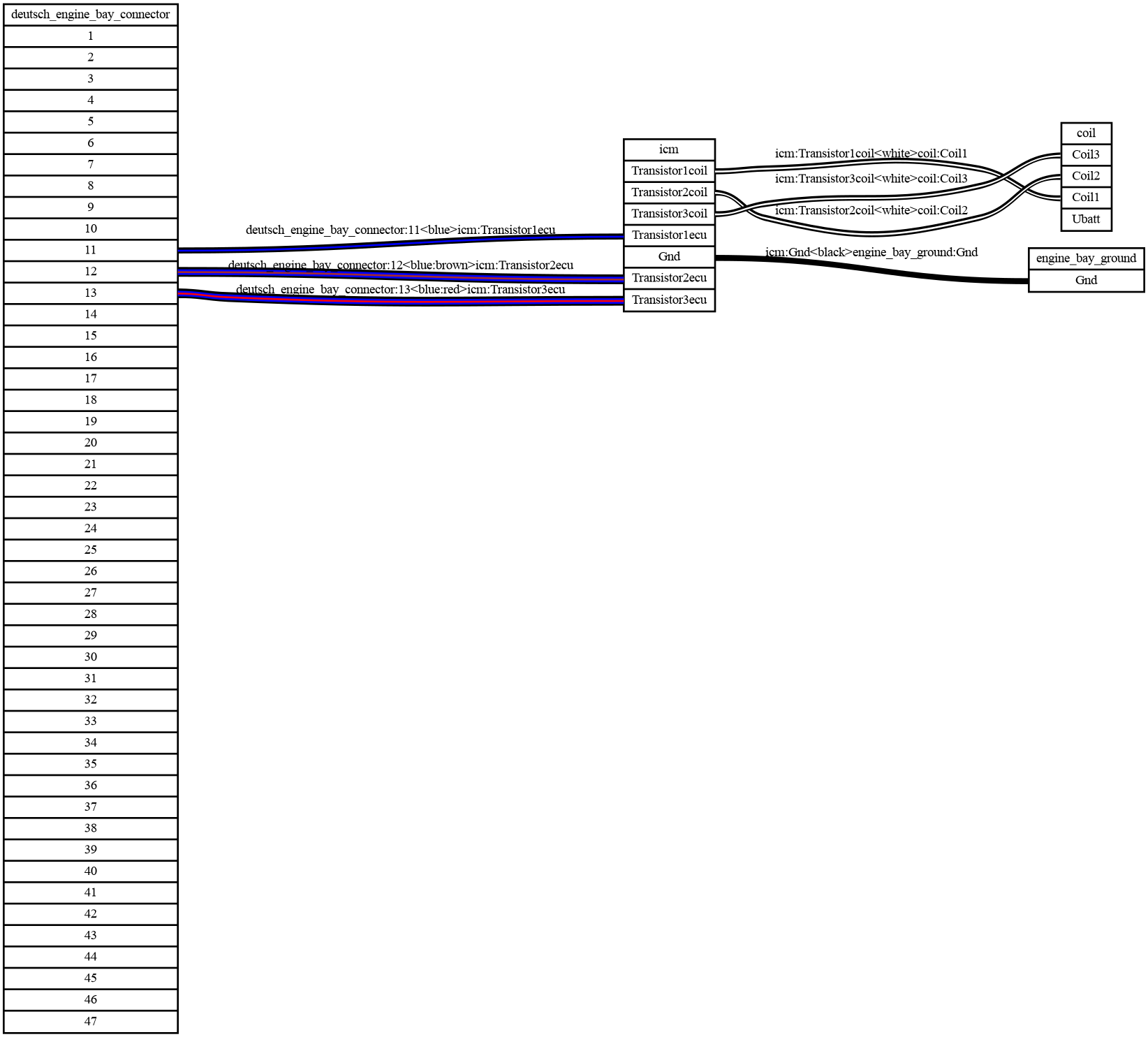
-
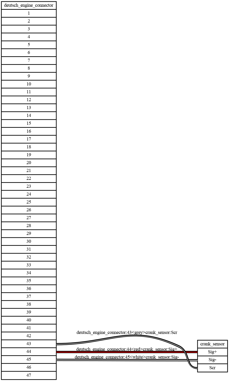
I recently purchased a Link Fury X and Razor PDM for a small winter project. I'm rewiring a 93 VW Corrado race car. This will be my first time wiring a car and I think I might have most of the wiring planned out. I would appreciate if someone could take a second look and see if anything looks wrong.
The image below is the wiring between the ECU and a Deutsch connector I'm planning to use to make pulling the engine easier. As an example the crank position sensor will use pins 7, 10 & 11 on the Deutsch connector which correspond with +5v, Trig2 & Shield/Gnd on the Loom A connector.
Theres also invidual graphs per node such as the various sensors and connectors if the image below is too busy in some areas.
https://github.com/djhedges/corrado_wiring

As an example.


(1).png.7b3f089ab63a6359b81649f6ec44ba84.png)


Brake lights based on pressure data from CAN bus?
in Razor PDM
Posted
Thank you, GP output was the missing piece of the puzzle. Maybe there is a way to play with timers & math to get the lights to blink?
This is what I ended up with which seems to work well.