


retro
-
Posts
36 -
Joined
-
Last visited
Content Type
Profiles
Forums
Events
Gallery
Blogs
Downloads
Posts posted by retro
-
-
Yes start of injection and 410 as a starting point you recommended earlier.
Ok so if we have an o2 sensor on the middle port 2-3 (there is only 1 exhaust pipe out the middle so only option)
then another sensor on 1-4 (these are individual exhaust ports)
As you are saying: If cyl2 (inner) looses fuel and gets leaner (by giving it to cyl 1= outer richer)
Then cyl 4 (outer) looses fuel and gets leaner (by giving it to cyl3 =inner richer)
Yes the inners cancel out, BUT wouldn't the outers also cancel out? The net result would be the same even with 2 sensors?
So having 2 widebands, one on the inner (shared pipe) and then one on the outer (likely shared if we put the bung down the merge of 1-4) Then we will be none the wiser...
I'm not sure how to get this dialed in then..
Or is the idea JUST have a bung on 1 or 4, then try get either of the individual ports to match 2-3.
P.S when changing the injection timing from 370 all way to 470 I didn't really see a net lambda change, but RPM went up and smoother at different settings..
I thought inners would be richer when getting injection timing wrong, because it would sit on the valve and wait for next cycle as described here.
The siamese port injection problem (starchak.ca)
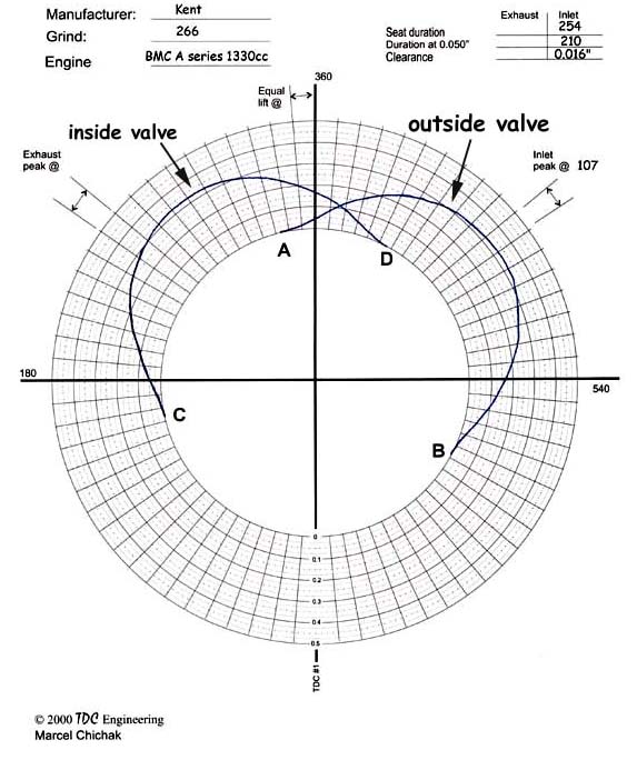
"from A to B the outside cylinder is sucking,
 from C to D the inside cylinder is sucking and
between A and D they share the port.
from C to D the inside cylinder is sucking and
between A and D they share the port.
the inside valve takes anything injected into the port from B to A which is 450° of the 720° port cycle or 63%,
the outside gets what’s injected between D and B which is 180° or 25% and,
they share between A and D which is 90° or 12%.
"
-
Got the car started and running on Sunday night.
The trigger offset was 360 out, but because wasted spark and quite lumpy cam it was a little tricky to spot at first as it was still happy running on 2 or 3 (maybe slightly on 4 haha) Checked exhaust port temps and plugs to find that.
Got that sorted and have the car revving and idling ok, my question is around injection timing.
I only have the wideband on the center exhaust ports 2-3. There is no bung on 1-4 for me to check currently.
Is the logic: if the injection time is too early I assume ports 2-3 get richer (as robbing the charge from 1-4.
If the injection time is too late the same thing happens?
Tricky to tune with only 1 wideband, but changing the timing from 410 to say 470 increases the rpm and slightly leans out mixture.
-
Appreciate the info, the owner has ordered a Bosch unit from pans, so should be quality not a knock off. Looks to be the same as the link/haltech also.
Yes if it was my car, id run a smart coil.
I started with the MX-5 1600 basemap as that appeared to closely match the fuel and timing curves this A-series will want. I just worry the 480cc injectors won't be big enough to maintain under 20% duty cycle with this aftermarket cam (we shall see)
The car is a fully restored classic mini van, full panel and paint in a nice white colour, a resto mod theme, black bumpers black mags, so I could prob post some pics info on it on ya social media or here once done.
I'll be putting it on the Dynapack and maybe make a whopping 70-80hp at the hubs
-
Dang, just wired the car. Oops looks like we adding an igniter, now to find something suitable, I see link do a 3 channel. We just need any 2 channel that will work with this dumb coil. Will prob just chuck a generic Hitachi 2 or 3 channel on there.
Hopefully haven't caused any issues with the ecu (all 4 spark plugs were sparking) but only run it at 200rpm cranking speed so far.
Rover MEMS - MPi/SPi (chez-alice.fr)

-
Hmmm I don't see an igniter anywhere in the wiring diagrams, so unless it was built into the rover mems ecu I assumed it was a smart coil with 4 pins...
Purple 'A' wire is switched 12+
Then the 2 outputs from the ecu to the coil. So technically only using 3 wires though..
Good point... crap how is rover triggering the dumb coil then... maybe some high coil drive direct from the ecu?
I'll measure the primary and secondary coil windings and see if there is continuity of any sort.

-
haha yeh this post is getting big, I was tempted to make my own post for getting this car working, but ah well if anyone else fits a Link to a Rover Mem MPi mini they have the joy of wading through all of this
However we have a custom 36-2 crank trigger and now a different cam trigger also so its kinda meh.....
Ah yes I forgot the EVO has a different cam trigger my bad.
Yeh regarding the timing light I think next time I'll work the light, I'll change by 10 and see if it changes as what he was describing doesn't sound correct to me.... Its the factory timing teeth on the lower cover, they are teeth marked in 4 degree increments but each valley would be 2 degrees so id say he just reading it wrong.
Coil is the factory MPi wasted spark unit.
You have possibly mentioned it already but this post is getting big - what does it have for coils/ignitors?
NEC100710 - Mini Coil Pack | Mini Ignition | minisport.com Mini Sport

-
Thanks for confirming everything Adam, and I'm glad everything looks good.
Just to note its an mitsi EVO cam sensor and all the G4X EVO basemaps have the trigger 2 edge set to ALL. (was only reason I was suspicious)
1 hour ago, Adamw said:With wasted spark and a dial back type timing light the advance will be doubled, so it either needs to be set at zero or some have a "2 stroke" mode.
We initially used a dial back timing light, then grabbed a normal light to check also (as I thought the wasted would mess with the dial back lights calc).
Our reference timing was 0 TDC, we would expect twice the pulses yes so one at TDC 0 and one 360 out.
So using a normal light, but changing the offset by 1 moved the crank angle 2 degrees? (so twice the pulses yes but doubling the offset???)
Using a normal light I wouldn't expect a change in 1 degree offset to move crank by 2 degrees. (then again I wasn't working the light to confirm this..)
We confirmed -147.5 degrees with a normal timing light had it bang on 0 TDC.
-
Update: we removed 2 teeth from the 36 tooth wheel, away from the cam sync teeth and also tried to be as far away from TDC as possible (possibly not as much as we would have liked though) once we found the offset...
It seems we needed a -147.5 trigger offset to sync the light to TDC. (odd I haven't had to use 0.5 to get a car bang on before) changing the value by 1 seemed to change the light by 2 degrees? 0.5 value was 1 degree.... (I wasn't working the light, someone else was so can only go off that)
Also in the scope attached, why does it count the 2 missing teeth as "Tooth after gap"
I thought it should read:
1: Tooth before gap
2: GAP
3: Tooth after gap
But it currently in the scope says
1: Tooth before gap (looks correct)
2: Tooth after gap (but this is the 2 missing teeth AT the gap not after it)
3: Counting timeout (appears to be the 1 tooth after the gap)
How can we tell if we have the crank VR trigger wired correctly?
Note we are getting an RPM signal while logging and flashing no1 spark plug correctly (wasted spark) so no idea if we are 180 out of not yet... But our gap does indeed appear to be 147 degrees before TDC.
Also I notice we keep incrementing the trigger 1 error count, it incremented from 33 to 35 after we stop cranking (But i notice trigger 2 signal stays at YES)....
Should the hall trigger be set to falling edge or ALL edges (I would have through the clean falling edge is what we should be trigging off, not also the rising edge (or all meaning both right...)


-
"2 missing teeth is going to be harder to miss than a single missing tooth" Thats what I was thinking also...
I was going to place the gap away from the cam sync tooth (just as a best practice and technically the G4X manual still says to do this) , but yeh I'll also make sure that's well away from TDC. I'll just line the engine up and estimate it based on where the cam and pistons are.
P.S When setting up a 3 wire idle solenoid, I've chosen AUX3/4, but then noticed the output pins are labelled backwards (open/close) from the help manual. Also the label does not change when changing the active state high/low also (probably should as it changes the function of close/open)
Have a look and try")
-
Yeh just confusing when it says trigger 2=YES the whole time then NO when it triggers.
I was thinking it needs a pull down resistor so it reads 0volts or NO. Then a YES when it triggers up to 3.6volts.
sounds like not required as that’s how the EVO map is configured and wired (how we have it currently)
regarding how many teeth to remove from the 36 tooth. Any best practices? For example is removing 2 teeth likely to be better than 1 in terms of potential sync issues on starting or cranking, or high RPM.
-
Ok more testing tonight, checked the mitsi sensor the guy sourced and its a J5T23071A sensor which appears to be an EVO4-9 cam angle sensor (amongst many other vehicles)
I used the trigger 2 config your EVO 4-9 basemaps have. Wired as per the pinouts I could find online.
Supplying +5v, signal, and trigger ground.
Oddly we tried to test this on the bench with the link trigger scope and waving a screw driver across the sensor but got nothing.
So tried it in the factory cam trigger hole, setting the sensor up with 1mm clearance to the lobes.
So appears we have a pattern (scope attached) Signal stays at 3.6 volts then goes 0 volts once every 720 degrees.
Will the link support this as a trigger 2? (ideally we need to see NO then a YES for trigger 2 each time. But we have the opposite currently)
-
Thanks for the suggestions and replies, yeh and if anything with this cam, its prob lumpy as and I might need to use TPS for Y axis yet...
Good point about throttle open when cranking..
Ok ill let the guy know about the sensor. -
"So with the MAP sensor connected to one port the ecu will see 2 intake depressions on one crank rev, none on the next rev. "
yeh I was more meaning if the code was fine with seeing the two pulses close together like that, sounds like its fine. To achieve this, the guy would need to drill and tap the manifold and move the map sensor to a runner (which is suspect might cause a bit of an lumpy map signal at idle on this engine), then block up the original map hole. At that point we may as well just try the hall effect first.
The fuel pump hole in the A series is fairly small round hole around 20-25mm diameter (just going from memory) with one tapped bolt hole.
So not sure you would get the sensor to one side (depends how wide the Cherry hall is), BUT if it had a wide enough point (rather than a fine peg) it might sense the two lobes.
I believe the guy has got a mitsi sensor (unsure what model) reckons will fit in the hole. Else I'll give that GS100502 a go. Cheers")
Factory MPi crank sensor below.
Example.
-
Remember it’s Siamese port so we don’t have “one intake port” we have two runners that are shared. The map sensor from memory is in the plenum.
Or do you think it would still work?Good to know about the G4X code. Ah well if and when we get the cam trigger working I’ll still remove a tooth away from the cam sync, may as well just as a best practice.
it’s starting to sound like we might need to fab something else up else engine come apart

Question: The owner has found a hall sensor thats wider and will fit in the back of the block and appears to be the correct depth (or we can adjust it), the thinking is it would MAYBE sense the two lobes coming past (pointed at the cam)
Going to give it a try anyways as it might be slightly less sensitive to the gap than VR. Prob not ideal bolted to the cast iron block tho (temperature and vibration wise) -
Ahh sorry I forgot to mention the cam trigger wheel was bent in that scope so it looks horrid, we have since resolved that. Didn’t notice the polarity tho I’ll double check that.
Regarding the 36 tooth wheel, yes the intention is to remove a tooth. I didn’t want to remove a tooth before I knew where the cam trigger was (set it to multi tooth missing but not cross over the cam trigger tooth)
Since I don’t have a cam signal we haven’t got that far.
The custom 36 tooth trigger the guy made actually kinda mimics the flywheel design, with the sensor sitting in-between two rows of 36 teeth rather than pointing at the edge of teeth like I’d expect.. but it works as u can see in the skope even on a bent wheel haha. But it’s a steel wheel and moving much faster than a cam.
Agreed the cam VR triggers are usually much closer air gap.
hmmm so given a MPi ecu works with the OEM cam trigger like that. (Likely with quite a big gap) So at this stage to me it sounds like all fingers point to this aftermarket camshaft… either slot in the lobes cut too far or made of different Material.
I’m not sure the factory has the trigger 0.4mm away from each lobe though. Especially as the cam might be able to move side to side slightly. Being the cam sensor peg is 2.8mm in diameter and the lobes have a spacing of around 5.8-6mm on this cam. (In the pictures on the net all the cams look like the spacing is at LEST 5mm which would give 1-1.5mm gap.
Hmmm maybe I need to hit up all these UK people that messed with MPi back in the day on megasquirt haha. They prob skoped loads these things..
-
I've attached examples of trying cam pulse vs cam level as well as swapping the wires around on the sensor, lastly removing the cam sensor ad tapping it on metal.
In the second trigger log u can see there appears to be a pulse window of sorts but its only 0.2volts (mixed in with all the noise it prob wouldn't work changing the arming voltage....
Steve MPi Mini.pclx Trigger Scope - 2024-09-8 7;10;24 pm.llgx Trigger Scope - 2024-09-8 7;27;36 pm.llgx triger scope 3.llgx
-
hmmm a possibility I guess, but the factory cam is prob a chilled iron blank?
But the big question is, if the sensor does point between the lobes (which the owner says it does)
Should we be picking up a signal as the lobe wipes past the side of the sensor (on each side) I'd assume YES provided the gap isn't too big (and its about 1.5-1.6mm)
The odd thing is we are picking up basically nothing at all at this stage.. -
Thats cranking with the spark plugs out and grunty battery, it would at LEAST be getting 250rpm at a guess. (I could prob work it out from the trigger scope)
"I assumed the cam sensor just pointed at one of the lobes rather than in the middle but have never seen one in real life."
Hmmm yeh maybe it does point at one lobe, but why have two lobes seems odd....
I'd have to get in there and have a look myself (car is at the guys place 20 mins away) Then I could see if it pointed at 1 lobe and how far away it is.
" I wonder of they have made the cam out of cast iron or something"
Hmmm I would have thought that be just fine for a VR trigger? (no idea what the cam blank is made from )
-
Cheers for the replies Adam. Yes they had the cam made and copied off an MPI camshaft. It has those lobes and I just got a call from the owner that they are around 5.9mm-6mm apart (not super scientific measuring method but putting in drill bits/punches in the back there and seeing what fits the tightest between the lobes). (he's SURE they copied exactly off the MPI cam, but we don't have one here to measure the factory gap between the lobes.)
The factory flywheel gap for the triggers is around 4.8mm width (he's actually running custom a 36 tooth crank trigger with the same gap to the trigger teeth.
the peg on the trigger sensor(s) is around 2.7mm diameter.
So sounds like a 1mm gap for the crank a VR trigger... I was getting +0.8-1volt at the crank trigger while cranking (but that was 36 teeth at the crank moving over the sensor) at crank speed. So no issues with the crank trigger.
So that means the CAM has around a 1.6-1.7mm gap either side of the lobes which also seems a bit big especially when the cam is spinning at half speed of the crank.
All I got on the scope for the cam was 0.1-0.2volt noise at times while cranking... nothing representing a pattern at all. I THINK at times we MAY have got 0.2volts pattern for those lobes (but just mixed in with all the other 0.1-0.2volt noise its not really anything we can trigger off. -
I was just wondering in the chart that Adam posted, what "link injector timing" was.
The value you enter in the software is stated as BTDC crank degrees correct? 410 BTDC I can see on the chart for cylinder 1. (or 320 Link injector timing?)
Got the car wired up yesterday and I'm running into the exact same issue as the OP with no cam 2 trigger voltage at all. (VR cam 2 trigger) Removing the sensor and waving it over a trigger wheel shows voltage on the scope (4-6 volts)... So not a wiring or trigger setup issue
Hmmm wonder what the heck is going on with these MPI cam triggers (I need to find a pic of how the cam triggers as I didn't build the engine)
Unsure if its tooth on the cam, or a window, slot etc (but I get basically NO change in voltage on cam 2 trigger when cranking)
-
Ahh I think understand the diagram above now, I see cylinder 1 is 410 CRANK degrees BTDC, what's "link injector timing BTDC?" It looks like the injector timing in the software is entered with reference to Crank degrees BTDC?
Yeh, I'll just set a fault (ideally it would be an actual CUT while I'm testing but all good)
Looks like the only way to get this really dialled in is with injector timing set to table and 2x widebands, one on the inner bank one on the outer. -
Yes its a MoonsoonX and a mini MPI which has a crank and a cam sensor. (the owner has just let me know he's not running the factory flywheel and has an aftermarket trigger ring on the crank pulley) So ill need to go see how thats setup etc.
ohh good to know about wiring 1 and 2 to the single injector. I was just going to use 1 driver for each injector, but you saying software wise its going to be 2 drivers for 1 injector (kinda makes sense I guess)
Regarding the valve timing, hmmm this car will have an aftermarket cam with no spec sheet so I guess I ideally need to figure out intake valve open timing (engine is already built and in the car 😕.
In your diagram it looks to be 500 BTDC start of injection when injector 1 pulses?, ending at 360 BTDC (at that duty) But are you saying I should go with 410 BTDC as a start?
(Found this online, unsure if these numbers are correct though, (as correct as reverse engineering the code/factory map)
Rover MEMS Diagnostic and Remapping Notice it has variable injection timing based on RPM and load. Some those 500 numbers look about right vs your diagram, but notice the number range from about 500 around peak torque, up to 635 at idle! Granted thats with the factory MPI cam and engine.
Regarding the duty cycle, thats why they use 480cc injectors I assume, but even then shared to 2 cylinders its really only 240cc and then a small window to inject makes it smaller again, kinda only like having 100cc injectors or 480cc @ 20%
I can't remember off top my head but is there a CAP we can set on duty, (or just an error code over X duty I see) and I assume the reason is we will be injecting into a closed intake valve if we exceed this duty and the next cylinder will rob that charge, making one cylinder bank rich the other lean.
Am I correct about those 5 wire unipolar sensors not supported by link? (or maybe u can wire em up in a way to control em via 4 wire stepper?)
(anyways kinda moot as monsoonX doesn't support stepper motor)
Thanks Adam, i'll start making the basemap (noting the latest software doesn't appear to have a moonsoon 'sample map' So we open the honda K series moonsoon one (I mean any of them we can make work, just something to note as the other wire in's have a 'sample map') -
I'm about to setup a MPI mini with a cam and crank triggers, @Adamw did this ever get tested regarding the triggers?
Sounds like im gonna have fun with injection timing and making a basemap also...
the MPI mini has a 5 wire unipolar stepper motor for idle control also (I don't believe I can control with the link ecu?)
I've got the guy to rig up a Bosch 3 wire instead.
I know the injector size (around 480cc) but don't know injector offsets.
Any hints for creating the basemap or any CRITICAL things I'll need to get right (regarding firing setup, injection window etc) (I don't want to lean out one bank for example)
The guy only has one wideband bung, (from memory its on the middle bank of cylinders (2-3) -
4 hours ago, Adamw said:
My guess is more than a year, it is not being worked on yet, and based on others, it generally takes about 6 months to work its way through prototyping, and testing before it is released for production. There has also been demand to support the stock sequential turbos now that these cars have become more valuable so there are plans to investigate that as part of the update which may make it a bigger job than a typical bottom board update.
100% regarding supporting the sequential solenoids, else all those ppl are just going to jump ship to Haltech, or even just rock the old power FC (which in a way for a street car is KINDA ok if you can live without safety's but the stock FD doesn't have safety either)
Dang I sense some big scope creep there then... Ok It's sounding like I either repin for the newer plug style or make an adapter for a wire in.


Mini cooper mpi 1300 (mems rover ecu) 1998 trigger setup
in Customers Vehicles
Posted
Ahhhh yes that description is a "batch!!"
thanks for clearing that up. (I’m glad u are onto it haha)
yeh I was thinking technically u would have all 3 pipes with o2 sensors based off your description above.
but yes we will use 1 of the outers, no point putting the bung on the merge of the 2 outers else it wouldn’t help me dial it in as it would just work out the same as you describe above.