


Sutkale
-
Posts
158 -
Joined
-
Last visited
-
Days Won
1
Content Type
Profiles
Forums
Events
Gallery
Blogs
Posts posted by Sutkale
-
-
Thanks! 5 primary injectors clear but not quite how injectors 6-10 are wired. Injectors 6-7-8 to primary 7 and injectors 9-10 to primary 8?
-
Lifting this up. How do you wire the injectors in 5 cyl engines to get 5 cyl staged injection? This ECU has 8 injectors drive, so 4+4 injectors is for sure doable.
-
BTW is there reason why ethanol content sensor reads 3-5 % lower ethanol content than in reality. Running VP´s C85 race ethanol and Continental sensor reads only 80-81 % ethanol content. Same with pump E85, but 1-2 % lower ethanol content. C85 should be exactly 85%.
-
According to the log files I see no reason for bad tune as reason for blown engine. What actually happen to the engine - no info on that. Is reference ignition ok?
-
Thanks. Gotta check that. I think this is quite first versions of i88. If so, no wonder why having issues connecting to PMU unit via CAN 2.
-
Hi,
Is 6 pin round connector at ECU end CAN 1 and CAN 2 is DI 9 & 10?
Thanks!
-
12 minutes ago, Adamw said:
You can use the test calculator to see how a parameter will be sent out and what affects the mult/div/offset has on it. I will show an example for TP below. You can see TP is stored in the ECU with a resolution of 0.1%, but since you cant actually send a decimal point over CAN bus it is normal to multiply or scale it to get it into whole numbers - in this case we multiply it by ten. So 10.5%TP would be sent over can as a number of "105" and a TP of 100% would be sent as "1000" over CAN.
You can see at the bottom of this test calculator screen that if I have a PCLink value of 100 (%TP), the CAN bus data will be 1000 (using the default mult=1, Div=1, Offset=0):

Since you probably dont need 0.1% resolution for what you are doing, then we could divide that parameter by 10 so you just send a basic 0-100 number out over CAN. Again we can use the test calculator to make sure it works as expected, in this pic below I have now set the divider to 10, and you will now see my PCLink value of 100%TP is sent as 100 in the CAN data:

A frame is the 64 "bits" that you see laid out along the bottom of the CAN setup screen. How many bits you need for each parameter varies. For instance something like the Fuel pump status in the example above it can only be on or off (1 or 0), would only need one bit (this is the width). Something like ECT that needs to go from say -30°C to +150°C would need 8bits (8 Bits can do a number up to 255). In the motorsport world it is most common to just use 8 or 16 bits for most parameters. In the example of 16bit parameters then you can send 4 per frame.
This one depends on how configurable the other devices on the bus are. Using conventional compound messages our ECU's only allow you to send 1 frame per stream/ID. Most basic CAN devices are limited to this type of message. More configurable devices such as motorsport dash loggers (and I would expect your PDM) can use sequential messages which means you can send many frames using just 1 stream/ID. This video may explain some of this better than me: https://www.youtube.com/watch?v=2m34nQ4i6KQ
Im happy to help you set up the CAN if you give me a bit of a rundown on what you want to send/receive etc.
Thank you Adam, appreciate! I´ll make the set up as adviced and be in contact if results are not as they should be.
-
I am also in the heat of installing my PMD / PMU and configuring Vipec i88 and Ecumaster PMU accordingly. I want to control second fuel pump based on TPS % position, i.e. 2nd fuel pump should turn on when TPS is above 25 %. How to configure multiplier / dividers / offsets that PMU would see TPS % as it should (from 0 % to 100 %).
And some basic questions regarding the CAN:
1) Should "Frame" include only one parameter, like fuel pump in picture above?
2) Should every "Stream" to be configured under single ID or is ECU transmitting all the data under on ID?
-
Hi,
Sorry for stealing the topic, but my post is kinda of some nature than this one. I just purchased Ecumaster PMU / PDM and would like to control it via CAN from my Vipec i88 (Link G4+ software). What are the basic settings in ECU, for example, controlling the fuel pump / fan / etc. stuff by PMU that are now connected straight from AUX outputs? Step by step instructions please..
")
-
Strange the 5 Cyl Petrol Turbo in Volvo is noe any project already, its a hugh of this on the market. I run with the original ECU together with Link so i think its impossible to get it too work. Probably we need to have the Electronic Throttle connected to the Link ECU. Anyone who have idea how this should be done?
I am running Volvo 4 cylinder white block engine with Vipec/Link ECU, so no issues to control 5 cylinder white block engine that is basically identical to 4 cyl version. Crank is 60-2 teeth, trigger on cam - so basic set up with that respect. Autobox control would be an issue since it has its own ecu and it needs certain info from stock engine ecu to run properly (torque reduction during shift, oil temperature control etc.). I think you can get this on the road, but do not know how the autobox would hold. I´ve hear guys been doing set ups like this, but autoboxes haven´t lasted for the reasons above.
I agree, there would be market for this car in Europe.
-
Can you confirm you are using Sequential/Staged mode and not Group/Staged? To be honest I don't remember testing that combination before.
Scott
Hi Scott.
I´m using sequential / staged. Since the correction applied only to primaries, had to use quite high numbers to get desired results.
-
Did few days ago individual cylinder tuning (fuel) and noticed that only primary injectors are controllable. Any ideas when also secondary injectors can be tuned per. cylinder? Or is this doable at all?
-
Any ideas when we get firmware update that would support injectors over 3000cc at modelled fuel equatation? Running staged injection with 1200 plus 2300cc injectors meaning cannot benefit from VE fuel calculation.
-
Resistor pack with link G4+?
-
Sorry for replying late,
Simon, these are 2.2 OHM. Using resistor packs they cannot run for sure.
They need proper peak and hold type injector drivers.
I contacted ASNU for this matter and they routed me to FIC.
They accept that these wont work untill peak and hold drivers are used however, they agreed to do an exchange
for their high z injectors for xx amount.
What Link ECU do you have?
-
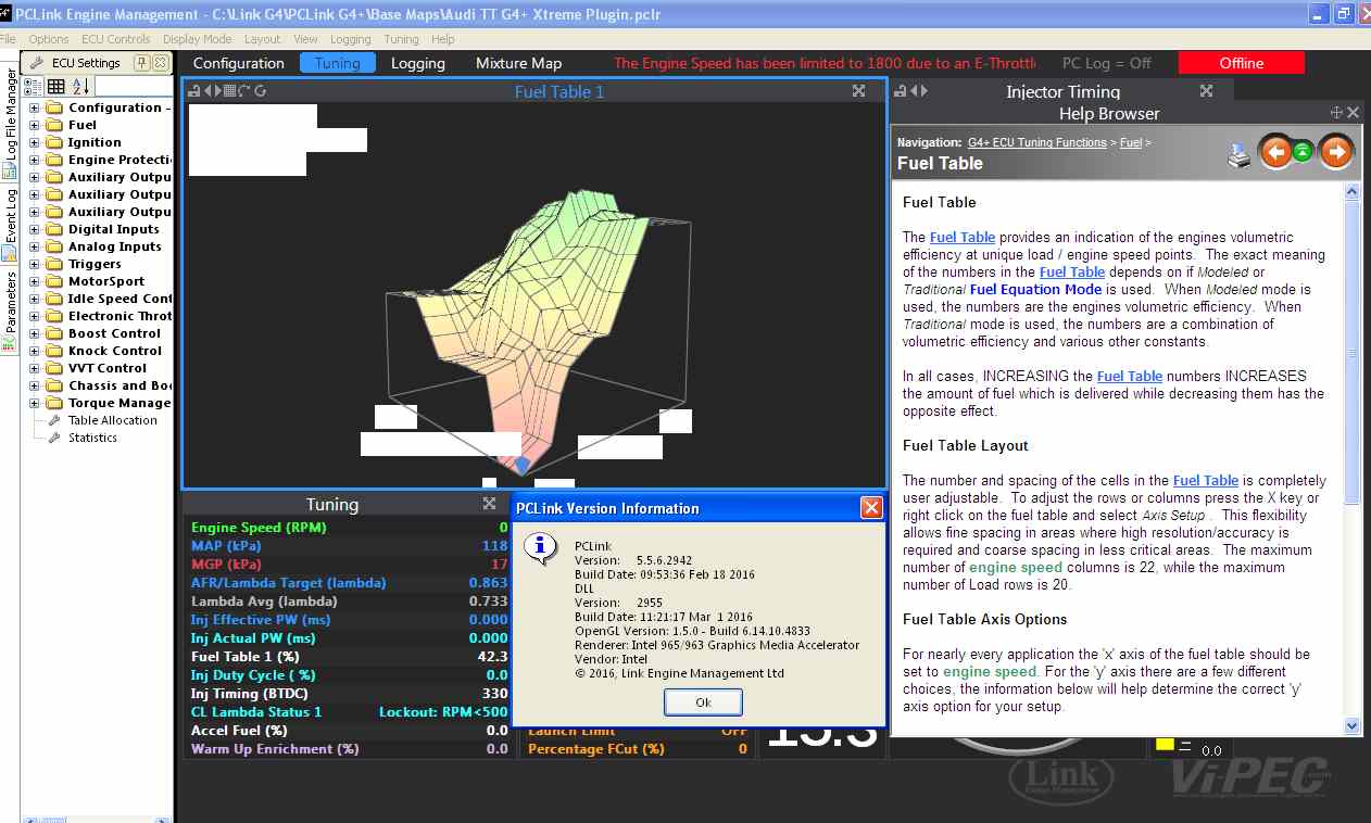
I have an old HP EliteBook 6930 and running Windows 10. I downloaded and installed an upgrade to OpenGL from this site and the graph works now.
http://danielkawakami.blogspot.co.nz/2014/08/gma-4500-series-feature-pack-for.html
-
this is only on my XP Laptop... Win7 64 is fine

I´ve got exactly the same appearance as above. Running Windows 10.
-
This may very well be related to what I fixed, I'll take another look and see if anything jumps out.
Cheers
I'm preparing a video that covers how to work with the new graphic view.
Can you post a screenshot of your graphic view and a screenshot of your Help>About window too please?Hey Jim, yeah this is a PCLink bug, so it'll show up in all basemaps while you're offline.
Here´s a screenshot from the graphic view that I see:
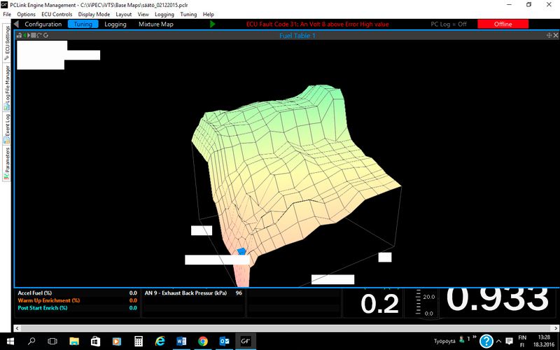
-
A bit different issue but with the newest firmware. I can´t get graphic view visible at the same time with grid view on fuel table or ignition table etc. And while looking at the graphic view only, the visibility is very blurred and can´t see any values. This all when offline. Haven´t tested online yet.
-
Files sent in two separate mails.
-
Hi Guys and thanks for watching,
Here´s the screenshot from TC settings, slip threshold is 5% at every gear:
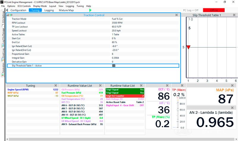
The log file is too big to attach or am I doing something wrong. It´s quite big, over 40 minutes...
-
I´m running at ridiculously low numbers at idle, around 5. All injector data should be correct, but I guess very cammy engine with minimum vacuum causes this.
-
Thought to post a video from my traction control test a few weeks back. 1.5 bar low boost on wet and cool road (+6 C) at 2nd gear. This is fwd car with 2.0 litre engine equipped with Garret GTX4202R turbo. Highest power level 916 hp at crank so far @ 2.8 bar boost.
Should traction control sound like this? Really heavy banging in my mind. However, front tires stays within set 5 % slip to rear tires, so it really works even on very slippery conditions. Traction mode is "Fuel%Cut".
-
One thing came to my mind with respect Thunder. Is new ECU / software capable of running larger than 3000cc injectors at modelled fuel equation? Would be nice to run on pure VE fuel calculation. Currently the software does not accept larger than 3000cc injectors at modelled fuel equation. I´m running sequential / staged injection where primaries are 1180cc and secondaries 2300cc. Had a quick look to Emtron fuel calculation whereas user may configure both staged injector sets individually.


5cyl staged injection
in G4+
Posted
Great, thanks!