


Sutkale
-
Posts
158 -
Joined
-
Last visited
-
Days Won
1
Content Type
Profiles
Forums
Events
Gallery
Blogs
Posts posted by Sutkale
-
-
Hi, what Sutkale said in one of the above posts is right. I have tuned quite a few GTR's some with big cams and this works perfectly for me with all happy customers-good power and economy. Start with FUEL MAIN then set LOAD=MAP and OPEN LOOP FUEL TABLE TO ON. Then set up the A/F TARGET TABLE to the A/F you want at the various loads as you normally would. Then set the main fuel table to LOAD=TPS. Then ignition to LOAD=MAP. You may find when on the road you may need some unusally high timing numbers in the 80kpa to 100kpa area for example I have 38 in 100kpa and 41 in 80kpa around 3000rpm but it all works pefectly. The software is so good I run 30psi in our GTR and do not have to alter the fuel table-its so easy to tune on TPS. You will soon learn to trust it-just shake your head and believe.
Cheers, Grant.
Exactly. The main fuel table is pretty damn easy to tune with this set up. Once its done just alter the AFR target table, if you want to change your AFR values.
-
The ECU will need to see boost so you can add compensation if needed.
As the fuel calculation takes in to account MAP it will do some correction automatic. If more is required (usually is) then you use the 4D table to correct the fuel.
Ignition is the same but there is no correction unless you add a 4D table based off MAP or MGP.
Simon,
What´s the point of using 4D table with this kind of set up since the 4D table affects the main fuel table (i.e the numbers in the main fuel table could be changed accordingly?)..?
-
Here´s one way:
"You do not have to make it all that complicated as the Vipec ECU have a very powerful method of mapping this type of engine. You have the fuel table axis set to TPS and the AFR correction turned on. You then map the engine on TPS and the ECU will lookup the target AFR table to know how to change injector time based on manifold pressure changes.
You do not need a 02 sensor or wideband for this to work. It is all done with maths.
You set the fuel table axis to TPS, and then tune based on TPS, and the ECU looks up the AFR table to know how to adjust injector time as the load (manifold pressure) changes. No 4D or 5D tables are needed."
-
Hi, all
Here is the best comparison of fuel maps. It is absolutely same car, I had free time on dyno, and mapped it to the same afr as it was with motec ecu, all other calibrations are simmilar
including avcs.
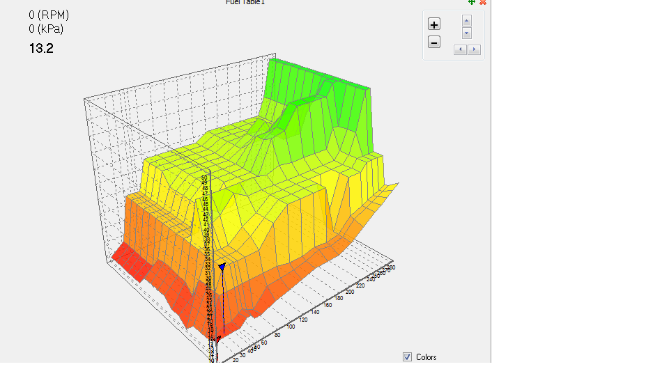
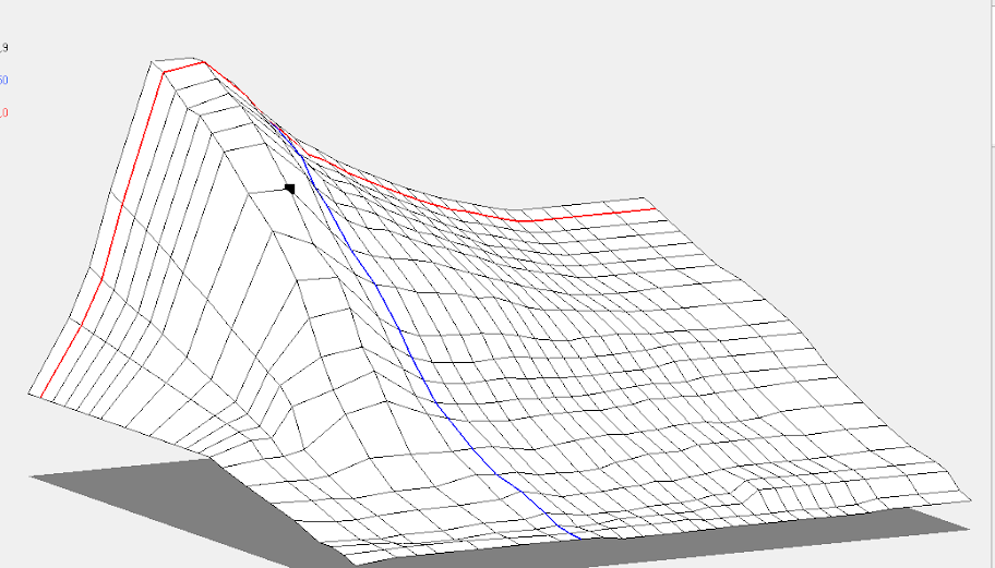
Maybe there are some spots where I did very rough tuning, but trend is clear.
And one more question, what is the difference between vipec, motec fueling and autronic? I tuned fuel in autronic ecu with only one sell in fuel table and target afr map.
It is impossible with vipec or motec. I think, that there is some kind of engine model, as tuner have to put CR in settings and injector parameters are rather strange.
P.S. Actually, I don't care what is the shape of the map, just want to know your thoughts.
This is what Ray stated a couple years ago about "one cell tuning" (bolding is mine though..):
"Chris,
The engine would need retuning.
The only cells that would be close, would be any you tuned at 14.7:1
The AFR correction should always be turned on before tuning. It makes tuning faster as the values in the fuel table are flatter. You can tune a cell at 3000 rpm and 100kpa and then copy that value over the whole table and the tune will be quite close for most engines. You then just have to fine tune some of the cells.
With AFR correction turned on, the ECU uses the air fuel ratio you have in the target table to apply a correction to injector time. The basis formula is based on 14.7:1 air fuel ratio.
14.7 / Target AFR Value = Multiplication value.
Example:- 14.7 / 12.5 = 1.176.
The 1.176 is correction used to offset injector time to achieve the AFR value in the table, based on the number in the fuel table cell.
It is possible to have a fuel table with just one rpm and load cell. The engine will run the correct air fuel ratio at all other rpm and loads. There is a video by Ben Strader from EFI-101 showing an engine on a dyno with one cell and a full table of cells. The power produced is the same and the air fuel ratios are very close.
Using the target AFR table has other advantages. You can change the values in the table at any time after tuning and the engine will run the new air fuel ratio. No retuning is needed.
Also this table is very good when tuning engines with big cams or multi throttle bodies. You set the fuel table axis to TPS, and then tune based on TPS only and the ECU looks up the AFR table to know how to adjust injector time as the load (manifold pressure) changes. No 4D or 5D tables are needed."
-
This is something that I´ve been eagerly waiting for.

-
What´s the fuel calculation method in this car? TPS or MAP as primary load source? Is the open loop AFR table enabled?
I´ve got TPS as primary load source (long overlap cams in turbo engine) and open loop AFR table is ON. This provides rather flat fuel table when the engine is on boost side.
-
As far as I´m concerned, N/A engines are always tuned TPS as primary load source. With Vipec TPS as primary load source for boosted engines works like charm also.
-
We have this is in stock, if you want to have a play with it.
Okay, I´ll call you one day.
-
Hi,
i am about to set one up also with a V88 on a heavily modified 2 stroke V6 outboard engine.
Very handy little display.
Regards
Dave.
Sounds even better. Gotta put this on the shopping list once the northern winter is over..

-
Thnx

-
Just wondering if Link´s display works with Vi-PEC ecus? Looks useful to me.
-
yup, I've got 2 wire solenoid and have ignored that setting and it works fine..
-
This CANNOT be used with a Multitooth trigger (no missing) on crank ? (And ofcourse a 180 deg half moon on cam). Am i correct? It needs a Multitooth+Missing on Crank ? (this is what the manual says)
:?
Yup, I've got 180 degrees "half moon" trigger on cam and 60-2 on crank and cam level works fine.
-
Under 1000hp from Supra is nothing...

Great work..
-
This turned out to be a hardware issue after all. Thanks for Vi-Pec / Link staff for replacing the ECU! 8-)
-
So I tried this calibration today and though I feel the results are closer to what they should be I think ECT now slightly underreads - my correction may be slightly excessive.
Sutkale, care to share more details on what you are seeing? Interested to hear about other set ups.
In my particular application the problem is that the coolant temp sensor is located in a "bypass" vein where coolant flow is highest when the thermostat is closed. When the thermostat opens, the waterpump then pulls most of the coolant out from the radiator and the flow in this vein should logically be lower than during the warm up period. As a result, it is possible that that coolant may always read higher in this vein than in the rest of the engine. Also, this vein is quite narrow, so if coolant doesn't flow through super fast then it may be getting heat-soaked by aluminium around it...
Well, the heat gun showed 75 degrees while sensor showed 125 degrees. In reality the 75 is the real one since I have 78 degrees thermostat, very cold I know. Currently I am in the heat of making tests to my wiring harness due to another reasons but this problem is to be targeted also. However, the readings are correct while the engine is cold and this makes me think the firmware update has something to do with this.
-
Let us know where you end up with. I suspect the same problem, even though I see even larger difference.
-
Hi again,
Is it this fault code you are getting?
74: Analog 5V Supply Error
According to VTS Help > VX ECU Tuning Functions > ECU Fault codes It should read between about 4.9 and 5.1 volts. So 5.05 volts should not be a problem. On the ECU I have connected for testing at the moment the voltage is 4.98v.
Scott
Yes! This fault code exists while runtime values shows 5.05 volts. I am gonna get a report today from my dealer how the ECU is doing in his test bench.
-
Hi,
It sounds like you have carried out the correct testing. Either return your ECU to your dealer for them to organise testing/repair, or email us on [email protected] to organise the testing/repair directly with us.
Kind regards,
Scott
Will do. My dealer will run this on test bench. Did another test yesterday with an external powersource but this time the voltage remained as it should be. Let's see what the test bench says.
BTW, on what level the +5v outvolt source should be? My ECU shows 5.05 volts (at runtime values) and puts out a errror code "5v supply error".
Thanks!
-
Do a firmware upgrade and run the map again. Might be a bug in the software.....if it doesnt work, its hardware related and non fixable

I've got the latest firmware installed already. :?
Vipec is supposedly made by humans, so it must be fixable. I've heard Vipec's customer service and guarantee is on high level and this will be fixed..
-
But if the ECU works if u have it powered from an other powersource, the problem must be in the cars wiring/powersupply :roll:
Did another test with an external power source (ECU disarmed from the wire harness) and the problem was there after a couple of minutes powering the ECU. Voltage oskillating between 24,5 - 6 - 0 volts. In my opinion this is ECU based problem..
-
Have you measured the supply voltage when the problem appears? That seems like a power supply issue, something wrong with the cars electric system, fuse, relay or ignition switch. When there is a bad cnnection somewhere, it starts to heat up and voltage drops....
Supply voltage is 12v constantly when the problem appears. This is checked from the supply wire. That makes this so weird as ECU sees different voltage than there is in reality. This makes me think this is ECU based problem.
-
Disconnect the ECU and connected the ECU directly with auxillary wires to the battery and ECU showed normal voltages. Also harness shows normal voltage from supply wire and ground wires are connected as they should be and showing 0,01 resistance. Connected the ECU back to the harness and the problem came back. I also disconnected different sensors but no influence.
Basically the problems begins after a while (app. 5-10 minutes) when the power is connected to the ECU. First 24,5volts and then to 0 volts. Great.. :evil:
ECU as powerwise has been working normally for as long as it has been installed but the problems came after a while I swapped to another engine. Whit this new engine the ECU did not have this kind of symptoms for a couple of weeks.
-
Yes, that looks like some MAJOR interference or some input is connected/setup wrong. I had same kind of issues when i had my trigger problems and got loads of errors and basicly everything was Fu**ed up- Its something simple, you just need to find it. How is ur Sensor grounds connected etc? trigger grounds?
Sensor grounds are for sure connected to ECU's sensor grounds. Funny thing is that this popped up even though the car has been nearly untouched...and had no electrical issues before that.
What kinda trigger problems you had? What did you do to fix the problem?


Itb with turbo - tuning strategy
in ViPEC V Series
Posted
Are you after the TPS based map? I´ll try to send you one. Just throw me your e-mail address.