jannerboy
-
Posts
30 -
Joined
-
Last visited
Content Type
Profiles
Forums
Events
Gallery
Blogs
Everything posted by jannerboy
-
Hi, Could I ask you guys to look into this one for me please? I appreciate it's been raised before here, just hoping you can update RealDash with the info? Cheers, John

-
The part numbers for the VAG R32 injectors are 0280 157 012 & 022 906 031J The part numbers for the VAG 2.8 4Mo are 0280 155 985 & 022 906 031F Really appreciate if someone out there has the link ECU data for either/both these injectors. Thanks. John.
-
You do not remove any resistors. You do not need to use a relay. Remove the instrument cluster and dismantle (3 screws) to get at the PCB board of the tacho. Solder a 1kOhm (blue striped) resistor onto the back of the existing resistor...see the second photo. Re-assemble and locate the wire in the loom at the blue plug connector. Cut this wire and attach a new wire to the Link ECU. Grant Baker then re-assigned an output to the tacho and it works perfectly. HTH, John


-
PCL file is attached. Hopefully you find the conflict. SeatIbizaCupra1.8t.pclr
-
Seat Ibiza Cupra with the Audi TT g4+ ECU. We cant get the ALS to work. We have added a switch to activate DI7 as ALS. Added the wire to the ECU with Sensor GND. I've attached some screenshots to get the discussion going. With the switch Active, all that happens is we rev up to 3000rpm+ with TPS 40%+ but the engine just continues to rev up to 6000 rpm or more before we quickly switch off the ALS! No ALS occurs. We have logged parameters and see that it "looks" like the throttle is following the target, and other parameters look correct! But clearly we are missing something! So something is not quite right...:-( Regards, John


-
moved the wire to pin 40 DI6 input and now works...just for the records...:-)
-
And as a stock MR2Link unit it shouldn't have anything connected to this. Thanks.
-
Guys. Which pin is the expansion connector?
-
Hi Simon. You mentioned three pins to potentially check and remove. Pin 28, 112, and the other one was ??? Cheers.
-
Hi, We have added a switch to DI9 Pin 112 and Sensor Earth Pin 27. However when switching we find in one position the system is active but in the other it flashes (switches) itself on/off continuously. Any ideas? We have set this up on other cars before so something is amiss. Pictures attached of our setup. Regards, John
.thumb.png.d634939e007173bd225c566a8115d0ba.png)
.thumb.png.59b3a4d9ac0e16bf7d7521482dc43dd3.png)
-
Can anyone recommend a dual USB Windows tablet to achieve this? Preferably with at least one full size USB slot. i can't find any suppliers of the Winbook TW series of tablets (in the UK).
-
Hi Adam, Thanks for putting us straight on that one. Is it wise to use knock control in this instance or should we change to a COP system? Can we change to a COP system with the plugin ECU on the ST205 in order to benefit from individual cylinder knock control?
-
Adam, Running latest firmware. Freq and Gain all set up by Grant. See attached for typical results. We only see knock on one cylinder... Should the stock (original) knock sensor work with the G4+ MR2Link V2-3 plugin? If so, ours doesn't. We then plugged in a wideband 2 pin sensor, wired up to the ECU (disconnecting the stock knock sensor) and we get the same result. Then wired a loom in separately to the ECU, same result. Then tried a different wideband sensor and yes you guessed it, same result... John
.thumb.jpg.dddc99ce91ed8a9ac95e7766077b732f.jpg)
.thumb.jpg.e04e4e062cd772967157c6fe9b8ce91a.jpg)
-
Guys, thanks and I've got the idle set up Open Loop, Idle Control On, and its now stable and does not now stall. The 1.8T needs 20 degs at idle (as per your base supplied map...). The key area was the E-Throttle 1 Target table. The e-throttle is very sensitve to changes around the idle areas within this table. At the moment the changes can only be made with 0.5 as a minimum step. Would it be possible to allow a step change at a resolution of 0.1 step? Column "0" of the Idle Ignition Table is set at 20, with Column "100" to "500" set at 25, and Columns "-100" to "-500" set at 15. I found that adjustments made in this table seemed to make no difference whatsoever...? I'll endeavour to turn on Closed-Loop and try that out soon, but i just wanted to run the above by you so you can advise if I have missed anything or anything else to check?
-
Guys, This issue still exists, and now its time to sort it out once and for all! Simon, can I ask for a more detailed "idle start procedure" for our car with ethrottle or clarify some points for me please? I can turn off the idle ignition control, and will wait until the engine is warm and try to adjust the main ignition table 1 to get a stable idle...some AFR adjustments may also be required i guess. But you mention "turn on the open loop idle control"...but I can't turn it off! there are only four options...none of which are "off". Did you mean "turn on the idle ignition control" to then release access to the idle ignition table? Then adjust the figures within during warm up...then adjust for idle ups AC fans etc...then go closed loop... Regards, John
-
Hi Scott, email'd! Thanks for looking into this. Log options that I chose shown below. Ahhhhhhhhhhh but ignore the CSV files as I found some ASCII characters have prevented loading into Excel. I've sorted that now and will send you three log files in an old EXCEL .xls format... This should be much easier to work with.

-
Scott, Straight answer. No. If I use the F1 key to fire the change the lights "flicker"...something else is preventing the lights from going out...:-( How do we make the change so that with the Link does the same as stock, connected we get:- Message ID 320 1st Byte. Stock it switches from 2 to 0...?
-
Guys, Here is the comparison image. Yellow is differences... The Link does not output message ID 588. Not important? Message ID 520 I think is also unimportant? It increments as I cycle the igntion switch? So we are left with :- Message ID 320 1st Byte. Stock it switches from 2 to 0, whereas Link its 3 to 1. Message ID 1A0 2nd Byte. Stock as described above but Link it switches as Stock but then switches back to 3.


-
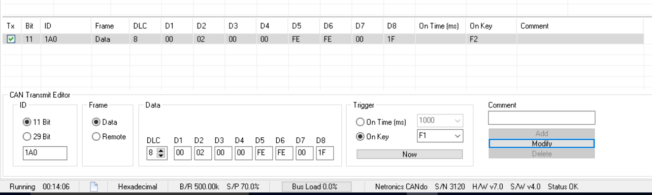
Scott, Grant, 1A0 is the message ID, 2nd Byte. It switches from 03 (IGN ON and ECU "talking" to the network) to 00 (IGN ON and lights out ready to start). It switches from 00 (IGN ON car running) to 02 when I push the ESP Traction Control Button. Tested by "firing" the modified 2nd byte using Canalyser as shown below. This is Stock ECU. I will now plug in the TT Link. Getting there...:-)
-
Hi Scott, Ok so I put back in the stock ECU and logged the data for ignition key on and to the point where the lights went out. There was no need to start the car as the lights go out after a short period. The first table is ignition on ABS ESP lights on, and then the second table is ABS ESP lights off. So we have the change BUT....there's always a BUT...the power steering light also enables/disables at the same time. So its not easy to decipher exactly which MESSAGE ID is the culprit. There are many changes from ign on to the lights off. As always this is a bit more complex than usual...BUT this is where you guys come in. You MUST have the data for an AUDI TT and a GOLF GTi for the CANBUS data, so you should be able to compare what I have to ascertain which MESSAGE ID is the culprit to save me ripping my car to pieces to try and further work this out! Ignore values in RED as they are what I call continuously fluctuating and not "switched". Green is "switched" and could be the ABS/ESP lights. But which MESSAGE ID and DATA value is the culprit? In fact I request some more direct help from your team who is the CAN expert, whereby you can Teamviewer dial in to my laptop live onto the car and diagnose this direct ASAP please? This is now taking a LOT of my time to sort out! John

-
Scott, many thanks for the upload changes. The Canalyser kit comes with an executable piece of software to check connection, and thats confirmed we now can see the Canbus network. Now to the small matter of sniffing out the data we need to fix this issue... Are you able to advise how to do this? Any links to forums, websites that a Canbus noob would benefit from seeing would be very useful right now! Cheers, John


-
The Seat Ibiza Cupra 2007 model, has the wiring for CanBus at the OBD2 socket. However, the CanBus module J533 of the vehicle does not output to the OBD2 socket. Apparently, which is really handy. Not. So I had to wire it up old school. So now it works.Good job I know how to use a soldering iron. Anyhow... We have the Canalyser software attached, and it works with the OBD2 socket. I want to attach files/pics but i can't which is really annoying....i'd love to show you but i can't. re-set my "attachments" allowance please.
-
Hi, We are struggling with this issue. I've attached the CANBUS wiring diagrams for the car. Also a word doc for the module unit descriptions. I'd really appreciate if these could be reviewed vs the Audi and Golf versions as something must be different! I'll post up the ABS EDL TCS ESP wiring diagrams in the next post as well for you to review please! Regards, John CANBUS3.pdf CANBUS2.pdf CANBUS1.pdf CANBUS4.pdf CANBUS Connections.doc We still have the ABS light on (and the ABS is functioning all the time) and ESP light on (and the ESP function does not work). I can't attach the next batch of files!
-
http://www.jti.uk.com/2014/08/toucan-available-for-link-g4g4-and-vi-pec/
-
Paul, Already in hand, but not had a response from them to date.


.png.fadf4243698e16c75e0c7aac71288d86.png)
.png.98f7d2b173eca42322cab31e25273940.png)
.jpg.e110220a839bcbc85aec9ff84c6adad9.jpg)
.jpg.5ff31dfa98f468efdc2ad4e41ae7e524.jpg)