Dochka
-
Posts
29 -
Joined
-
Last visited
Dochka's Achievements
")
Newbie (1/14)
0
Reputation
-
Yes Successfully
-
I did check that, But were afraid of feeding +12V to the digital input from the ignition switch, Shouldn't the Digital Input be fed Ground ? Thank You
-
Hi, Wanna enable this function in order for the Idle Stepper Motor to reset correctly, My question is about how to wire the Digital Input & the Auxiliary Output ; Is the Digital Input wired to a positive Ignition Switch signal ? as per the Wiring Diagram ? And where the Auxiliary Output goes ? To what side of the Main Relay ? Thank You
-
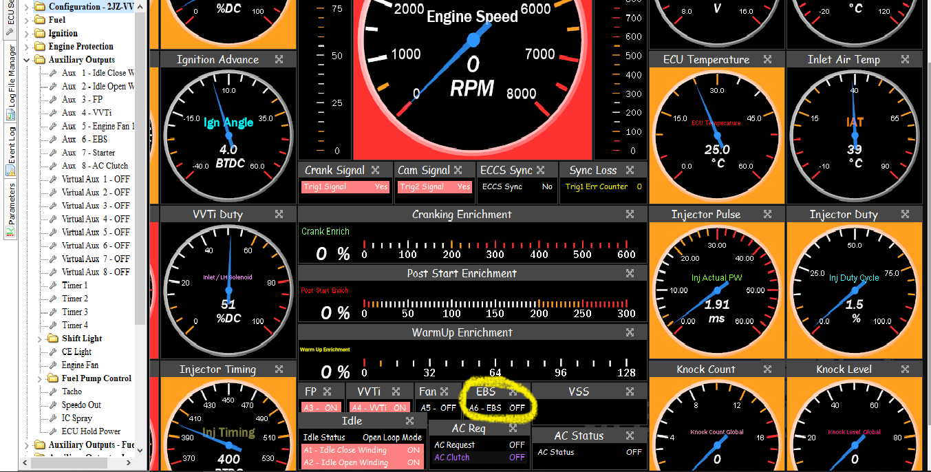
Hi, Trying to control boost using a MAC boost solenoid, Configured my dashboard layout, but when turbo spools the A6 indicator doesn't lit like the other indicators do .. Why is that ?


-
Crankshaft Sensor is a 3 wire type, Has a single external Ignition Coil "4 pin plug" GM Crank Trigger has 4 lobes I believe this is the same trigger as the Vortec 7400cc engine I Megasquirted 2 years ago, I did run it on sequential mode using "dual wheel" configuration with the cam sensor input from the distributor...
-
Thanks Adamw, The problem is that I didn't see the engine yet, I know it's installed in an Off-Road Jeep, so I assume it has a Returned fuel system at 3 Bar, equipped with a distributor with spark plug wires, stock sized injectors (200cc/min), a crank sensor reluctor... But I thought you can send me a start up file in advance so I can be prepared... Will send you more details once i have them Thanks Again
-
Stock, Old Truck engine ; Fitted with a Crank Sensor, Distributor and Stock Injectors
-
Hi, I've got a Link Storm Black ecu to run a Chevy 454 Stock engine, Anyone's got a base file for it ? Thank You
-
It has one Start/Stop button, that has a "ribbon printer like" terminals at the back of it ; I mean that I have to know which one of those terminals is the "Start" signal and not the "On" one, so I wire it to Digital Input 3, and then find what is the terminal of the "Stop" Signal so I wire it to the Digital Input 4 wire so I use it as a Kill Engine
-
I wired DI 3 to the "Start" end of the [Start/Stop Engine Button] and configured as follows ; 'Function : Start Position' , 'Pullup Resistor : Off' , 'On Level : High' DI 4 to the "Stop" end of the [Start/Stop Engine Button] and configured as follows ; 'Input Latch : Off' , 'Pullup Resistor : Off' and 'On Level : Low' And used Aux 7 as "Starter Solenoid" , 'Polarity : Low' and 'Driver Type : Low Side' Is this correct ? Thank You
-
Tested the output directly from the ecu plug All of the injector outputs are working Did some detective work on the wiring loom and found out the problem... Thanks
-
Yeah, I first thought so, But I got shocked when I tested the Voltage on Injector 1 and 6 Plugs while testing them and found out that Inj 1 Output Voltage is 0.60V and returns to 0.20V when I stop testing and that Voltage on Injector plug 6 is at 0.20V all the time even if i test it... Injector 3 plugs is the only other one that works (0.20V to 0.60V) , while all the others left don't work... Checked the connector, wiring... Strange thing is that engine was running normal before I updated the firmware... Tried restoring the old firmware, and the same issue persists...
-
Hi, Today I've got a car powered by a Toyota 2JZ-VVTi engine managed by a Link Storm Blue G4+ 1 Plug ecu ; Engine was running normal before we shut it down, I Reset the ecu to factory settings and upgraded the firmware to the latest; Set up all the Inputs/Outputs,StartUp.pclr Engine is wired Semi-Sequentially, Inj-Coil 1 run Cyl 1&6, 2 Runs 2&5 & 3 runs 3&4 Started the engine, but 4 cylinders are dead... Turns out Injectors number 2, 4,5 & 6 are not pulsating Checked wiring continuity and no issues there, but when I test Injectors individually, only 1 & 3 Pulsate... Coils work fine What could be the issue ? This is driving me nuts, tried running the engine 36-2 mode on Trigger 1 only but same issue.. Elios_X Trigger Scope Log 2020-02-24 8;42;59 pm.llg Elios X.llg
-
The car had all the electronics and wiring removed before, What should the PT-Bus wire colors be ? Are they Orange and Black or Red and Blue ? Also, the car has a Start/Stop Engine button in the dash that I'd like to use and keep the car as factory, but the DME ecu has been removed also... Is it as simple as wiring a AN Volt Input or Digital Input to the Link from that Start Button and then from Link to the Starter via Aux 8 for example ? Thanks
-
Thank You ! I changed the Trigger 1 Settings to Reluctor and for now set the Trigger 2 to "none" Everything works great