Scott
-
Posts
2,257 -
Joined
-
Last visited
-
Days Won
70
Content Type
Profiles
Forums
Events
Gallery
Blogs
Everything posted by Scott
-
Hi Søren, Here is a diagram: The pins to use on the MAP sensor will depend on the MAP sensor you have. Scott

-
Hi Elia, You can enter the short pulse width data into the i88 Audi TT ECU. The correct location for this is ECU Settings > Fuel > Fuel Setup > Injector Setup > Injector Short Pulse Width Adder Table If you do not have this table visible you may need to upgrade your ECU firmware. Scott

-
With high impedance injectors I would not expect any problems with being compatible the Monsoon. Have you tried increasing the master fuel number? Have you verified fuel pump operation and good fuel pressure? If you can record a PCLog of you trying to start the engine and attach it with your base-map we can take a look. Here is a video on how to do this: https://youtu.be/_P1LRANeO4A Scott
-
The engine fan system does vary across the Evo 4 to 9 models. Most Evo 4 to 6's will have the engine fan work by grounding pins 20, 32, and 34 through Aux-Ignition 4. Some Evo 7 and 8's and all Evo 9's will control the engine fan by applying a PWM signal to pin 21 via Aux output 1. I believe 100% in the duty cycle table will give 0% fan and 0% in the table will give 100% fan. The relationship is inverse. Scott
-
It will work, but ideally the Vi-PEC should be on firmware 4.10.2 before bringing it through to G4+. You will need to be online with the G4+ ECU before you can open the vipec base-map file in PCLink for G4+. Scott
-
The ECU will apply the dwell time from the dwell table regardless of ignition mode selected. So on wasted spark if the table had 3.5ms then each time the ignition drive activated (twice per two crank revolutions) it would have a pulse of 3.5ms. And if on direct spark if the table had a value of 3.5ms then each time the ignition drive activated (once per two crank revolutions) it would have a pulse of 3.5ms. Regards. Scott
-
We will test TriggerScope on a red G4+ Xtreme and come back to you with the results. I don't have one here right now, so Simon will likely do this on Monday. Have a good weekend. Scott.
-
Thanks for the new logs. One thing I noticed in the unsuccessful start log is that 'Prime Fuel' (pre-crank prime) shows as 0.0ms. Where-as in the successful start log the prime fuel is 29ms. The Pre-crank Prime only occurs for the first time you crank the engine after the ECU powers up. From what you said in your first post the engine doesn't start on the first attempt, but then does on later attempts. Try turning pre-crank prime off and see how this affects the starting. Scott
-
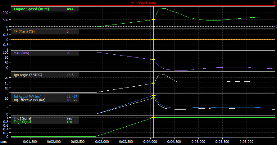
Thanks for the logs. When looking through them it looks like the MAP reading is varying between the two logs. This is then affecting the amount of fuel being injected and the ignition angle being applied. Successful start: Unsuccessful start: The logging is at 10 Hz, which is fairly slow and may explain the difference. Would you mind changing your logging rate to 40 Hz and doing the logs again? Scott


-
You want the yellow ( <- Wrong) brown wire (output) of the LC-1 and this should be connected to the Analog Volt input of the ECU. Scott
-
Andre may have misunderstood. Aux outputs 5 to 8 when driving high can only supply 0.5 amps of current. If switching a ground they will do 2 amps. Scott

-
That is strange. I think you're right, if the ECU is seeing cranking speed rpm correctly then it must be seeing the trigger signals. Maybe try clicking ECU Controls > Restore to factory Settings. Then load your base-map into the ECU and try TriggerScope again. Scott
-
Hi Brendon, You should update the offset numbers to the values obtained from the cam angle test. Scott
-
Hi Paul, Can you please PCLog and successful start and an unsuccessful start and upload the logs? Also please upload your base-map. Here is a video showing how to do PCLogging: https://youtu.be/_P1LRANeO4A Scott
-
Hi Mark, Looking at the Analog Inputs section of your base-map I see you have An Volt 4 configured as Narrowband Oxy. Is your O2 sensor a wideband type unit? If yes, and it is wired to An Volt 4, then An Volt 4 should be set as Lambda 1. Fuel table 1 has axis of engine speed and MGP (Manifold Gauge Pressure). If the cell in the fuel table is only moving horiztonally then this indicates that the ECU is not seeing the MGP reading (from the MAP sensor) changing. If you look at the MAP or MGP readings do they change when you change engine conditions? What do they read when the key is on and engine is off (and you are connected to PCLink)? Scott
-
If you had the ECU on firmware version 5.6.4 and then loaded in a base-map from your hard drive that was from firmware 5.1.1, the ECU would try and correct the base-map to suit the new firmware. Because that is quite a jump in firmware versions and the newer firmware (5.6.4) has settings that didn't exist in 5.1.1 the ECU may not correctly allocate these settings. So if you load a base-map from older firmware into an ECU on newer firmware make sure you check all the settings. Scott
-
I'm happy to ask the engineers if it is possible. Do you have some examples of motorbike engines and what trigger patterns are found on them? Yes, this is possible. Here is a video showing how to do this, and some other cool functions of the 3D table view: https://youtu.be/Eo9zBcIkacs Scott
-
Yes you are correct, the firmware is tied to the ECU and not the base-map. When you do a firmware update it updates the tune in the ECU, but not any previously saved versions of the base-map on your hard drive. Scott
-
Has the ECU been unlocked yet? The trigger signals are disabled until this is done. Scott
-
Thanks for the screenshots, I see what you mean. I'm happy to ask the engineers to consider something like this. Scott
-
For 3D tables with adjustable axis (just about all of them) it is possible to convert the table from 3D to 2D by entering Axis Setup (x key is the shortcut) and turn one axis off. This will allow you to view the remaining data as a 2D graph. This works on for a 3D table with one or two lines of data, but is not really useful for larger tables like the main fuel and ignition tables. Scott
-
I see you are on firmware 5.1.1, I would consider upgrading PCLink and firmware to our latest as there have been changes and fixes to TriggerScope. Either way will work and Link tuners differ in which method they use. As you will have some form of MAP reading from your vac box I recommend trying the method described on the 'AFR/Lambda Target Table' page of PCLink Help. If you have the injector deadtime and injector short pulse width adder data for your injectors then I recommend using modelled fueling. Aux Output's 5 to 8 are able to supply a maximum of 0.5 amp current per channel when high side driving. I think it is very likely that each solenoid will draw more than this. I recommend using an aux output to activate a relay that switches on both VTEC solenoids. There is no way to view a 3D table graph as 2D other than rotating the view so you view it side on. Scott
-
Edited: I just read your last post better. If you have 6 teeth on the crank (Trig 1) and 1 tooth on the cam (Trig 2). You should be able to set the Trig 2 sync to 'Cam pulse 1x'. Scott
-
1) and 3) I don't have a lot of advice for which head unit or app to use. I have used the Torque app before, but not for much time. 2) We have good success using the PLX Devices 'Kiwi' OBD2 to blue-tooth devices. 4) For the CAN H and CAN L wires you will want to use normal automotive cable (doesn't need to be heavy duty). Twist the cables in a braid with 25 to 30 mm between twists. This following PCLink help pages will be useful. Scott. ECU to OBD-II wiring.pdf CAN bus wiring.pdf
-
Hi Mark, For a modelled fuel setup in the Link ECU, you can setup a lot of the settings before even running the engine. The more accurate the information the better. Things like the injector flow rates, dead times, short pulse width data, fuel stoich ratio, engine capacity, base fuel pressure, fuel density and injector rated fuel pressure can all be set up before hand. Other things like Fuel table, fuel charge cooling coefficient, and charge temp table really need to be done with the engine running. As you've noticed the modelled fuel mode does not have a master fuel number. All the additional settings used by the ECU in modelled fuel mode mean it is no longer necessary. The 'Lambda 1' reading will display only in lambda units when in modelled fuel mode. When in traditional fuel mode 'Lambda 1' can be displayed in AFR or Lambda units. If 'Lambda 1' is still reading 0.000 all the time then upload your base-map and we'll see if we can identify the problem. HPAcademy is certainly worth looking into they offer some good value courses on our ECUs and also general tuning. Scott