Rich RDE
-
Posts
150 -
Joined
-
Last visited
-
Days Won
6
Content Type
Profiles
Forums
Events
Gallery
Blogs
Everything posted by Rich RDE
-
This is a very common engine to setup. You will need a trigger on the cam to give it a position sense. You can use a older LS cam where the sensor is in the rear or you can use a newer front cover sensor. You will have the 24x reluctor. Do you have a base file already? If not please email me at [email protected] and I can help you get this going. I am busy tuning all the time. But check emails frequently. RichRDE
-
Scott, I will get a PCLog of this tomorrow and let you know how things turn out. I thought that this was the case the the 360 optical but it was giving us some weird issues. I also want to check the ECCS Relay. The car seems to not want to turn off once turned on and then trying to shut off power. I need to look at some relays and see how the power is being switched here. Other than that. Seems as we may have this running a KA24de in the S-chassis lineup here shortly. Rich
-
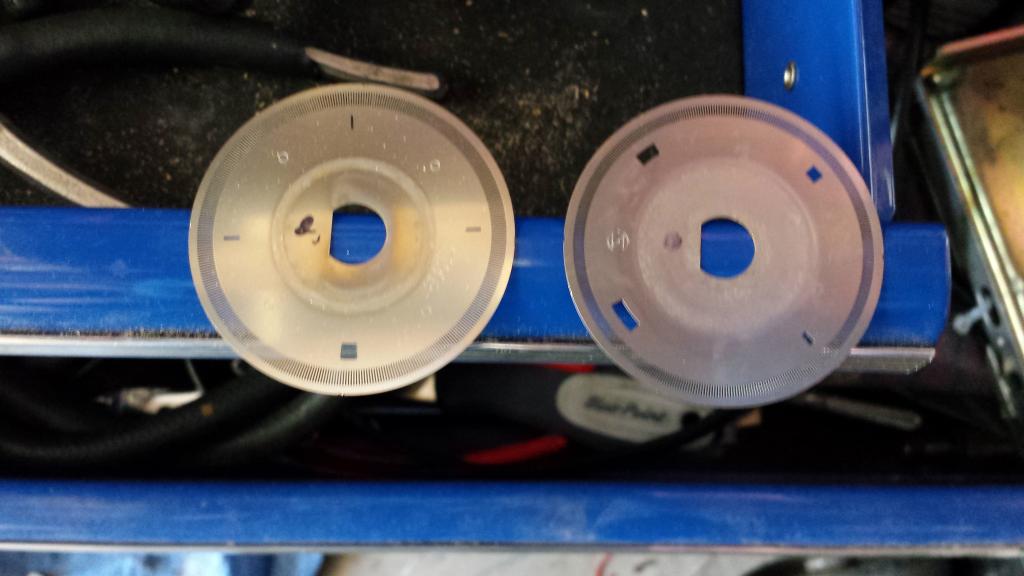
Hey guys, So here in the US we are trying to experiment with the S15 ECU running a KA24DE turbo in a S13 chassis. The wiring for the ECU pin out for the Dual cam KA24DE harness is the same. We ended up swaping over the Coil and Igniter from the Dual cam. But the Internal disc is different. After connecting the ECU we were getting everything to work well and calibrate all the sensors except for the trigger 1. This picture shows that the Disc inside the CAS is different in the SR20 engine vs the KA24DE engine. I do know that when calibrating the CAS it will green light for both trigger 2 and ECCS. Any thoughts? This would be huge as we could market this as a unite that would function for guys running dual cam KA24DE turbo cars who need standalone options! Cheers, RichRDE

-
I have seen bits of metal and shavings floating around and just has some gum up around the sensor itself that was causing a similar issue one time. Double check that before digging deeper.
-

subaru V4 wrx 98 ej20g 440cc map wanted 4 link+storm
Rich RDE replied to 98subaruwrx-gf8's topic in G4+
Email me at [email protected] I can setup a remote session and get you squared away. Not a problem at all. -
You want to make sure that you log all the PID's here and keep an eye on what the corrections are doing like Simon has mentioned. Seems as there are some things to consider in the tune. Are you running closed loop fuel controller or straight open loop? Factory injectors? Lean conditions at idle can be a multitude of things. LOG LOG LOG.... post one. Everyone here will do their best to steer you in the right direction.
-
Reece13, I can help you out no problem. This is very easy to do as you can put the signal wire from the map to a analog channel input of your choice. I used to tune a lot of adaptronic stuff and the old software of their's in comparison to Link software is very old school. So I can understand the comment about it being more advanced looking. You can just delete the AFM all together. If you email me I can help you get this going. Do you have a base file? [email protected] is my email address. Cheers, RichRDE
-
You should log some of the PID's and also log the target position of the throttle plate. Most of the time when Idle becomes so inconsistent I switch strategies to open loop method of control and the car becomes much more stable. It just takes some logging and patience when tuning in the E-throttle control.
- 1 reply
-
- 1
-

-
You can order these connectors and pins through a company called Digi key. I do this as some customers only request a certain amount of pins and like to keep things as neat and tidy as possible. www.digikey.com Pins part #455-2051-1-ND Connector part #455-2154-ND
-
Differential fuel pressure is what the main calculation goes off of for fueling in modeled mode. So this would be why the axis is setup as mentioned by Mapper.
-
David doesn't this change when going to FP sensor only support a rising rate regulator? I would imagine that this would only be the case if you had a FP control that you boosted DC too that you would not need the vacuum line to the FPR? Maybe I am mistaken? Seems as he is using a 3D table for this and the FPR is still rising rate? Still does not explain why the Fuel pressure is not reading which it is now trying to use as a main calculation in the equation.
-
As of right now I do not believe it can.
-
All sounds pretty solid. Where is the map sensor hooked up? So the issue is the differential fuel pressure here and now I understand a little better what is going on. In the modeled equation it is calculating Base fuel pressure - MGP which gives you your Differential. The ECU needs to know the correct dead times at your specific given fuel pressure to compensate for. You need to give it your base fuel pressure to start with and make sure that is correct. You have the axis setup correctly. What's interesting is how the differential fuel pressure drops as the engine starts to go into that weird oscillation. Something seems a bit off to me. Can you email me a log? Also if you could supply your base file or the fiel you are using so I can take a peak. All the firmware up to date? I still find it very odd that the ECU does not see the Fuel pressure. Is this correct? Have you pulled up the run time values to verify? [email protected] Cheers, Rich
-
Checked air gap, checked filter settings, rewired so the shielded wire is not connected to ground wire, and checked polarity? Can you post your base file? Or PM me with it so I can take a look. Also post a log file trying to start it with your settings. I hope I can help.
-
Oh yes ok.... Did you check the polarity of the sensor? Making sure the wires are wired correctly? You getting any interference with other high power wires and the signal wire not shielded properly? Maybe the air gap is causing an issue? Filter set correctly? The bare wire is the shield it should not be connected to the ground wire. Try running the RX8 trigger selection within the ECU.
-
Post a trigger capture. Is this the RX8 sensor? The wiring could be reversed if so. Pull up the Run time tab and look at trigger sync error.
-
It seems as though you have fuel added to your warm up enrichment. You will want to set your IAT correction and Warm Up Enrichment table to all zero when in modeled fuel equation mode. High 90's is a tad high in modeled. Just depends on the rest of the engines characteristics and settings. The dead times correct? Small pulse width adder? This engine seems pretty cold as well and it is going back and forth between warm up enrichment and when getting cold is throwing off the Charge temp. coefficient table. Zero those tables out and give that a try. Do you have AN volt 13 as a GP pressure or set to fuel pressure? The ecu is a bit confused. Post a log file so we can take a look. Cheers
-
I am very excited to see the CAN coming out. This will make things even easier for setup and tuning. Link does it again!!! Great job guys.
-
I would opt. for the new AEM X series gauge. I have placed one in the 1jz-vvti RX7 we did twin charged and it is very consistent and stable. My guess is the controller itself is just starting to slow a bit because of its age. I also really like the new PLX series wide band sensors with touch screen gauges. Both in my opinion are great. If money is not an option and you want top of the line NTK air fuel monitor. Hope this was helpful. Each one have their own unique features. -RichRDE
-
90% of the time it is most likely caused by faulty hardware as suggested it is most likely the sensor itself. Keep us posted. Hopefully easy sensor replacement for this issue.
-
You should be able to calibrate the denso 3 bar with the 3 bar map sensor config inside the pull down tab. If you choose to go with the 7 bar then you will need to choose the 7 bar setting. Cheers
-
I am sorry I totally failed to look at the part number on the picture. The first three numbers represent weather or not it is 1,2, or 3 bar. You have a 1 bar GM map sensor. The 4 number in the last 4 numbers represents 199* so this was manufactured in 1995. You are looking for #749 part number stamp which will be a GM 3 bar sensor.
-
Did you do a Map Sensor calibration and store after selecting the right configuration? If the map sensor is calibrated right it will give you a message saying calibration complete. Or an error message. Maybe you have something adding additional fuel in your tune. Hit R for run time values and look at the fuel section to see if any trims are active. Post a log.
-
Hi Moshi, You will want to just select 3 bar map in the pull down menu for the what aux channel it is on. Then go to the Map sensor calibration and calibrate. That should do he trick for the GM 3 bar. As for the wiring. Have a look at this diagram. This should get you all squared away. -Rich RDE

-
You can absolutely remove 5% depending on how rich it is. I would say that would be plenty and get the fuel settled.