


S4-VR6
-
Posts
29 -
Joined
-
Last visited
Content Type
Profiles
Forums
Events
Gallery
Blogs
Everything posted by S4-VR6
-
erroneous trigger causing ignition cut and erratic tach
S4-VR6 replied to S4-VR6's topic in Vi-PEC i Series
To ground. -
erroneous trigger causing ignition cut and erratic tach
S4-VR6 replied to S4-VR6's topic in Vi-PEC i Series
Hi Adam, I finally was able to get some time to do this simple test. I was able to see a signal from the ECU into the signal converter, the test light flickered but just barely. At the tach I was able to see a signal but it was not flickering like at the ECU output, it was just solid on. Does this suggest my tach is toast? Thanks! Bob O -
erroneous trigger causing ignition cut and erratic tach
S4-VR6 replied to S4-VR6's topic in Vi-PEC i Series
I assigned and wired ign 8 to the input of my signal converter as a tacho signal and still nothing. The tach still sweeps on its own so I am not sure if it is damaged or not. Any other thoughts or things I can try? Thanks!! -
erroneous trigger causing ignition cut and erratic tach
S4-VR6 replied to S4-VR6's topic in Vi-PEC i Series
Hi Adam, I am running firmware 4.10.2 which appears to be the latest, can you confirm? Thanks!
-
erroneous trigger causing ignition cut and erratic tach
S4-VR6 replied to S4-VR6's topic in Vi-PEC i Series
Hi Adam, I don't have Tacho as an option in my ignition drive menu? Is it something I can add? here is a link to the tach adapter I have. https://www.diyautotune.com/product/axm-100-high-voltage-tach-adapter/#tab-ywtm_78211 Thanks! Also worth mentioning that I wired the tach directly to the ecu using Aux 3 set to tacho and at one point the needle drifted to the mechanical stop and stayed there until I shut the car off. The tach still sweeps under its own function when I turn the key on so don't believe the stepper motor is damaged but I cant be sure at this point. It never did a thing when I wired it to the adapted.
-
erroneous trigger causing ignition cut and erratic tach
S4-VR6 replied to S4-VR6's topic in Vi-PEC i Series
So I got bored this weekend and decided to pull my cam sensor to see what it could see. I took some photos using a mirror and it looks like I have the early style with only one tooth. Would this suggest my setting for Trigger 2 are correct at 1x cam pulse? Is there anything else within my trigger set up/calibration/ignition set up/dwell or just in-general set up that you see as an issue? For the tach, do I hook the spare ignition drive directly to the tach input and leave it set up as an ignition output? I assume leave the tach set for 6 cyl? Got a bit more aggressive with boost settings so now I really need a tach... Thanks!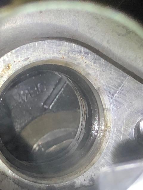


-
erroneous trigger causing ignition cut and erratic tach
S4-VR6 replied to S4-VR6's topic in Vi-PEC i Series
I believe the stock is high voltage. I purchased a tach that is also driven off the coil that did not work. after a little research I tried a signal converter from DYI Auto and it still didn't work. I did a brief search for a low voltage driven tach but had not luck. Is there a way to confirm cam teeth with a capture or is it inspection only? The picture you provided is likely what I have (embarrassing that I don't know, long history...). If I assume it is, what would be the next step? Thanks!.jpg.e924edff15eb7aaa23170085f452339a.jpg)
-
erroneous trigger causing ignition cut and erratic tach
S4-VR6 replied to S4-VR6's topic in Vi-PEC i Series
Perfect, will do. Does everything look good with the waveform or do you see something else that needs to be addressed? On a different note, do you know of a tachometer that can be driven by the v88? Thanks, When we started this conversation you mentioned my trigger set up looked suspect. I am still currently using them in as they were in the config file I shared. Do these need some attention now? Thanks, -
erroneous trigger causing ignition cut and erratic tach
S4-VR6 replied to S4-VR6's topic in Vi-PEC i Series
Well I think I finally got it. Quick run down if anyone cares. First waveform displayed inverted crank but good cam. Second waveform still showed inverted crank and cross talk to cam. I retraced all my steps and was able to re-produce the first waveform (inverted crank, good cam). I then rolled my signal and ground in hopes to invert it and ended up with the cam waveform on both channels, or what looked like cross talk from the cam. At this point I started to question my second waveform as crank cross talk and started to examine my connection to the ECU. After adjusting the probes (staple and paperclip) over and over I was finally able to capture this waveform and there are no trigger errors accumulating at high RPM or erroneous tach spikes that I have observed yet. In hind sight I must not have inverted the wires like I thought the first go around. It looks like it shifted the crank profile to a valley from a peak on the falling edge. Does this correlate into an advance or retard of the spark? At this point, should I re-calibrate the trigger offset and delay? I really hope to get your blessing, finally, then it is off to the tuner for some real boost! Thanks a million for the continued support! Bob O
-
erroneous trigger causing ignition cut and erratic tach
S4-VR6 replied to S4-VR6's topic in Vi-PEC i Series
Thanks for looking this up! This confirms what I measured with my meter and is how it was wired when the trigger error was gone, the signal was not inverted, and cross talk was on the the cam sensor. According to the manual, the figure in section 8.1.1, the sensor ground and shield are tied together and wired to the sensor ground pin on the ECU plug. Therefore it would not matter what pin I moved it to, center or right, it would ring out at the sensor ground pin at the ECU Plug. My cam sensor ground is also wired to this pin, figure in section 8.1.2, and this is what I believe is the source of the cross talk. Doing this did not invert the signal, just induced the cross talk... Did I miss-interpret the figures or missed a nuance potentially? Thanks and sorry for being soo slow... -
erroneous trigger causing ignition cut and erratic tach
S4-VR6 replied to S4-VR6's topic in Vi-PEC i Series
The part number to my crank sensor is BOSCH 0261210107. "Neither the + or - pin on the sensor would have continuity to ground normally". How is this the case, in your first diagram the - pin is wired to ground? are you referring to chassis ground? If Roll the + and - then the + is on the sensor ground and creates the cross talk as demonstrated in my second waveform capture. Again referencing your first diagram above. I must be missing something... I rang out all the wires and have not found an issue yet... all grounds and shields are to sensor ground and sensor inputs are wired to the ECU. Is it safe to conclude that my cam sensor was working properly according to my first wave form and the crank sensor is still where I need to focus? I plan to hook it back to the scope today or tomorrow and stepping through this again and to see if I can see the inverse wave form, which I have not been able to produce. Thanks! -
erroneous trigger causing ignition cut and erratic tach
S4-VR6 replied to S4-VR6's topic in Vi-PEC i Series
In plug A there is a shield ground and a sensor ground and those need to be wired as such correct? i.e. my shield from the crank sensor to the shield pin and my -ev to sensor ground pin? The cam sensor has no shield so ground it to sensor ground not shield ground. The cam sensor is a Hall sensor and the VW wiring diagram shows it wired to 12vdc. I did not realize this and wired it to the +8V pin (which only measured at 4.6V with the key on), do you anticipate this being an issue? My MAP is currently wired to sensor ground, is it ok for all three of these to share this pin? The reluctor wiring diagram in the manual shows the shield and -ve tied together for a reluctor which would make it impossible for me to reverse the crank sensor polarity without putting in the sensor into the ground circuit and hence create cross-talk, at least that is how I am interpreting it. (pg 29 of the manual). I rolled the wires back but do not have the scope to test today but I am not expecting any different results than the first waveform I sent because i have now returned it back to the original wiring. In your first diagram above I am sure you meant to tie the -ve's together and not have the sensors in series? Thanks! -
erroneous trigger causing ignition cut and erratic tach
S4-VR6 replied to S4-VR6's topic in Vi-PEC i Series
So you believe I have the positive and shield swapped now, I will double check. Should the Cam sensor should be a square wave and the Crank sensor have the "S" shape? How would the crank signal effect the cam signal? Is there anything else I can check? Thanks! -
erroneous trigger causing ignition cut and erratic tach
S4-VR6 replied to S4-VR6's topic in Vi-PEC i Series
Hi Adam, I rolled the crank position sensor wires as suggested and my trigger error at high RPM is gone!!! I tired to run the configuration available in the help file we have discussed and it still would barely idle. The car is running better than ever using my config and seems pretty close. Any ideas why? Attached is the updated waveform with the newly wired crank sensor. It seems to have changes the cam sensor profile as well, is that what was expected? If you could let me know how this looks and if I need to address any other anomalies. Thanks!! Bob O
-
erroneous trigger causing ignition cut and erratic tach
S4-VR6 replied to S4-VR6's topic in Vi-PEC i Series
Thanks Gents! I will correct the wiring, that's an easy fix. sure as sh!t, the probe I was using was a 10:1. I assume this should be a 0-5v signal? I will roll the wires, adjust my probe, and grab another capture this weekend. Looking at probe B, it is also a 10:1... does that make sense or are all bets off due to wiring issue? What should its voltage be? Thank you again!!! Bob O -
erroneous trigger causing ignition cut and erratic tach
S4-VR6 replied to S4-VR6's topic in Vi-PEC i Series
Hi Adam, Attached are a few photos of the O-Scope signal i was able to capture. take a look and let me know what jumps out and what I can address to remedy. Thanks very much!! Hi Adam, I forgot to mention that scope A was wired to the cam sensor and scope B was wired to the crank sensor. Thanks,.jpg.0a6f2410d459129d89131051f88a29bd.jpg)
-
erroneous trigger causing ignition cut and erratic tach
S4-VR6 replied to S4-VR6's topic in Vi-PEC i Series
Sounds good. Do I need to adjust any parameters like arming threshold and capture the affect or can we determine all pertinent values from the capture at idle? If all I need to do is capture the signals at idle, no need to reply. I am planning on hooking it up the scope tomorrow. Thanks!! -
erroneous trigger causing ignition cut and erratic tach
S4-VR6 replied to S4-VR6's topic in Vi-PEC i Series
Ok, I will hook it up to my O-scope at work and get some screen captures, hopefully this week. What do you want to see? The help file configuration that barely kept the engine at idle or my configuration where the engines runs better. At idle, rev'ed to where trigger error starts, etc.? I would prefer to only have to do this once if possible so any guidance will help. what potential "things" will make it unhappy? Thanks very much! -
erroneous trigger causing ignition cut and erratic tach
S4-VR6 replied to S4-VR6's topic in Vi-PEC i Series
After adjusting the settings to mimic the help file the motor barely ran (very rough idle and would not rev easily, seemed like ignition timing was way off, no backfires either way) and I was accumulating trigger errors slowly. I have a stock coil pack that is a single brick with 6 wire outputs. Direct spark seemed to make sense but it likes wasted spark a lot better, not sure what the internals are. I did replace spark plugs not long before this issue seemed to appear, but to be honest, I am not sure how long the problem has been there, unknown to me... I was hopeful that this was going to solve the problem, what do you recommend next? Do you believe it is in software or physical? would replacing both sensors be worth while? Thanks! -
erroneous trigger causing ignition cut and erratic tach
S4-VR6 replied to S4-VR6's topic in Vi-PEC i Series
Hi Adam, I adjust the drift with the delay correct, not the offset? I thought the offset would change my idle timing. what about the: Alloytec vs Ecotech? I dont have Ecotech as an option? Does VVT stand for variable valve timing? That is a confusing trigger mode since I do not have variable valve timing. Do I need to perform the VVT set up or is that to determine the trig 2 offset which is 74 ATDC according to the pdf. How does the 4 cog cam come into play? My main ignition offset in the calibration screen is currently 275, could that make sense (not very close to the approximate 9 in the pdf)? Lastly, what about the digital inputs and auxiliary outputs? I am not sure what to do with those setting. Did I read/interpret correctly that since my cam position sensor is wired to trigger 2 that I do not need to configure a DI for the cam sensor? Thank you sir, your help is truly appreciated!! VR6 Engine Specific Info for Vi-PEC.pdf -
erroneous trigger causing ignition cut and erratic tach
S4-VR6 replied to S4-VR6's topic in Vi-PEC i Series
Hi Adam, I now see the option for the trigger mode to be set up as Holden V6 Alloytec III VVT but not the Ecotech as suggested in the attached PDF (I wish I had found that earlier). I also was under the impression that VVT was for variable valve timing, which I do not have so I never investigated. I can change all my setting to match this PDF no problem but I am confused on the DI 1-4 and the Aux 1-4 set up. I have my cam position sensor wired to trigger two and not to DI 1-4 and I do not have a VVT solenoid to wire to Aux 1-4? VR6 Engine Specific Info for Vi-PEC.pdf I also noticed my ignition set up did not match the PDF and I was not applying a delay. I will also correct this to match the PDF and try to measure the delay per the instructions. How does this correlate to the Trigger Offset, which one needs to be adjusted first (they seem to do similar things)? When I started this project I had no clue what to look for when building the motor and what to apply to the software... probably pretty obvious. I can tune fuel and ignition timing, its all the other small details that I lack experience in. I feel like I am close! Thanks again!! Bob O -
erroneous trigger causing ignition cut and erratic tach
S4-VR6 replied to S4-VR6's topic in Vi-PEC i Series
Hi Adam, Excuse me if this is trivial but I do not see an option for a Holden Trigger mode and there is no option of cam pulse 4x? How can I set it up as you suggest? I am sure my cam has 4 teeth the photo indicates. I hope its as easy as a setting. Thanks Very Much!!! Bob O -
erroneous trigger causing ignition cut and erratic tach
S4-VR6 replied to S4-VR6's topic in Vi-PEC i Series
Hi Adam, you are correct, I do have a V series. My apologies. I have access to an O-Scope, I will try to hook it up and get a signal capture. If it is a waveform issue, what would be the tell-tale within the waveform and what can I do to remedy it? I have tried changing filter levels on the triggers but did not seem to change anything. Could it be a trigger calibration issue? Could it be spark plugs? Have you seen similar issues were it looses its mind at higher RPM and regains composure when the RPM comes back down? I tried to attach a zipped file of of a data log. Here is a second attempt. Thanks very much! Bob O Log 20-07-21 7_05_59 pm.zip Hi Adam, Attached is a tuning .pcl opposed to a log, maybe this is better? thank you again, Bob O S4-VR6_150_A_Rev_3.2.1.pcl -
Hello, I was hoping to get some help on a trigger error. Motor is VW MKIII Vr6 I started to experience what seemed to be an ignition cut while at mid range RPM. I noticed that when it would go into this cut mode the tach in the software would bury itself at 8k (max) momentarily then return to actual engine RPM. When it did this I received an RPM limit activated error and the ignition cut the same way it does when I actually hit the RPM Limit. My first thought was that the crank position sensor was starting to act erratic, but I am not convinced. Observing the run time values I am seeing trigger errors starting around 3800-4000 RPM and increasing until the engine falls below 3800 RPM. Since day one I have always had a miss at idle that I have not been able to tune out The car starts pretty easy and does not miss at idle for the first 10-15 seconds when its cold, then the miss picks up and does not go away throughout the ECT range. I would be greatly appreciative if you could take a look to see if anything jumps out and to lend a suggestion or two at what to look at next. Attached are a couple logs. The larger file is a non aggressive driving log. The smaller file is me revving the engine in neutral to demonstrate the problem and is probably a little more to the point. Any help is most appreciated. Kind regards, Bob O Log 20-07-21 6_52_03 pm.zip Log 20-07-21 7_05_59 pm.zip
.thumb.jpg.bca44bcc124562e60ae1d696313da1df.jpg)
-
Hey Guys, I recently finished swapping a VR6 engine into my S4 and was able to successfully start and run the engine. While I was going through my second heat cycle and getting ready to drive the car out of the garage i noticed a rear main leak which brought the project to a temporary stop. I am getting ready to pull the engine now to fix the leak and wanted to reach out to the community to see if anyone had a base-map for a VR6 engine. although my engine was running i noticed my ignition table seemed to advancing the spark too much for its given ECT (in the range of 20Deg BTDC) causing a high idle, poor reving, and bad throttle response. I am sure I can adjust the ignition tables (and others) to get it to work but I was hoping to bypass the unwanted run/idle time associated with tuning these basic parameters. Ultimately i want to fix my oil leak, start it up, and break in my engine with a decent chance of success and not have to worry about backfiring, nock, poor driveability etc. Thanks!


.jpg.e924edff15eb7aaa23170085f452339a.jpg)


.jpg.0a6f2410d459129d89131051f88a29bd.jpg)
.jpg.03507a30b8b1b4fe697b0093459be1d4.jpg)