


SteveX
-
Posts
29 -
Joined
-
Last visited
Content Type
Profiles
Forums
Events
Gallery
Blogs
Everything posted by SteveX
-
Hi guys, currently running a RV8, fitted with a h404 cam. I can’t find the specs on the cam but understand it has a large overlap. Car has been mapped and is making great power and running well, but it stinks on tickover (no cats). It’s running as lean as poss on tickover, so I can only assume fuel is coming out of the exhaust ports. It’s currently been upped to 340 from 330, but my question is, how much further is OK? I moved to 350 and no issues at idle it would seem, how far can I go? Just trying to minimise the rich fuel smell on tickover, but not sure of the negative effects of having the injectors so close to TDC. Thanks!
-
Thanks Adam, no worries, I haven't had chance to load in and test yet as I've been busy, will do when I can and let you know, many thanks!
-
Thanks for the reply, if I go ahead with it i’ll combine the two switch grounds to one 2a fused wire going into the aux output just to make it safe in case of any surge. Cheers.
-
Hi Gents, I've got a spare fan that was fitted on my old charge cooler rad (that appears to have not even really been wired in right) so I figured I may as well fit it to my new rad seeing as it's going spare and wire it in properly. I wasn't going to bother originally as I didn't want to block flow (it was fitted as a push style fan) but the part number shows it's a davies craig fan that's fairly decent and can be reversed, so I spun the blades around and will reverse the polarity that way it shouldn't block flow but make a nice pull fan. The previous person who fitted it just piggy backed the fan off of the rad fan on the old charge cooler > pretty useless tbh. It was originally hooked up to the ECU though, as I see what appears to be a fan control on Aux 5, traced the wire, it does go into the loom and off somewhere but I am 99% sure it was originally the charge cooler fan and when the kit was fitted to this car the loom was broken on that wire and not used. Anyhow, my car originally also had an engine lid fan which was pulled out by the engine builder for some reason, I might get another one and stick it on the lid. I've got some standard 30A 4 pin Bosch relays. Just thinking of heat soak sat in traffic in summer. I'm thinking of using the ground part of the switch circuit on aux 5, but I wanted to know if it was fine to piggyback two grounds to that one aux (since I'll trigger both off of a combination of ECT and IAT). Just planning to pull the same 12v ignition feed to each switch side of the relay's them combine them to the one ground on switch to the relay from the the Aux. It sounds OK to me, there will hardly be any current, I believe the link can take 3A, so no problem for just a feed with nothing drawing on the switch circuit, but figured best to check here if people have switch two relays on one Aux fine before. Thanks, Steve
-
Spot on, well the air tests seemed fairly good, so I'll try liquid and that should verify it then, thumbs up.
-
Thanks Adam, it’s an open type element not a coolant style sensor. Would the water damage it?
-
Hi Gents, I’ve been going round in circles trying to find out why he IAT is slow to respond and always high. I pulled the sensor today and that is when I found it is an FAE one and was reading 28 degrees when ambient was 16-17. To test, I blasted very cold compressed air on the sensor, it took a while to change to around 22, but then started to climb to about 23 again whilst cold compressed air was still blowing on it. When I stopped, it quickly climbed back to about 28/29 which I knew was not ambient. I set to Bosch 017, ambient then showed 17, I went to my other car and checked, it’s outside temp sensor was showing 18 ambient, but the FAE one was outside in the cooler breeze so likely very close. I went for the same drive as I did with the other setting, IAT’s showed 44% less and it was more responsive. I did a few more tests, got a thermometer, ensured the output of a hairdryer and low and high settings, the FAE sensor read within 1 degree of the thermometer when being heated at the same distance for the same amount of time. i feel like the FAE one is within spec of the 017 Bosch sensor close to 1 degree on each test with the thermometer. To be sure I went to buy an 017 but can not find them anywhere. Whilst my tests were rather crude, upon changing the setting again after the sensor had cooled and was outside the car it again showed 17, if I changed to the original setting it would show 29, no way again was 29 degrees outside. Checked my other car outside temp sensor, it showed 18. Does anyone have any other ideas for teasting, or where I can obtain the 017 sensor? Would you be happy that with the test I conducted the 1 degree difference is negligible? Certainly better than a 44% difference! Thanks, ‘’Steve Edit, also FAE sensor showed 1.68 k ohm at 20 degrees
-
Thanks Adam, you are a star, attached is the PCL. mr2.zip
-
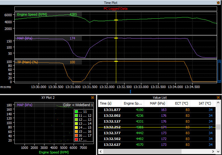
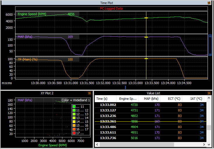
Hi, It's set to open loop, it's a MAC 3 port, activation 1500 rpm, 100kpa MAP, 20hz. I just checked some old logs at wastegate pressure, I guess it is stable, average 60kpa, fluctuates here and there up or down by 1 kpa, so 59 then 60 then 61 then 60, a couple of peaks at 62. With my setting, it will peak at around 76 on boost when it spools up, and will vary with lows of 69 sometimes less, it won't hold a steady 76ish. I'm looking at a target of 11psi, so close as I can get to 76kpa solid. I am working on the charge cooler system, and need to know that I can maintain steady 11psi with no pipes blowing off etc, and control IAT at a ramp run with stable pressure as close to 11 psi as I can before the final mapping. I did assume perhaps the wastegate duty cycle is too high low down, but it's a gt28 on a small-ish engine (1.8) so i'd like less pressure seen at the wastegate early to allow a bigger hit when spooling. The setup somehow seems to allow the boost to spike, then it settles down further on. This is a tweaked one, it was around 27 across the board to start, then dropping to 26, then 21, then 0 in case of spikes. I'm going to try and move the duty cycle up to 28 higher up the RPM and in the lower cells to see if it will bring the boost back up but not sure. I need to try and get 11ish PSI fairly stable then I can dial in the settings. I've got the softcut set at 80kpa, so not much room for a spike, but I don't want to spike as high as 11.6psi anyway. You can see below it peaks at desired 76, but then is a little unstable eventually dropping 1 kpa at a time until it hits 69, then fluctuates 1 or up or down, quite a big difference, I only get desired boost at spike when first spooling on full throttle. Thanks for your help! Steve

-
Thanks Adam, sorry have been crazy busy re assembling the charge cooler system and building heat shields. I’m on my mobile right now but will message you the map soon. That’s a good point, i’ll check at wastegate pressure but can only do that when the car is back together. Thanks, Steve
-
Hi All, I'm trying to find a way to stabalise boost with the G4 Currently using a Mac 3 port, with open loop mode, RPM activation 1500, 100 kpa. Table is set up with RPM and MGP. I know there is a dead zone with the solenoid, so <10% doesn't really do anything. Wastegate pressure is 7psi, target 11psi max. Duty cycle for the solenoid set to 27% from 1500 RPM, the plan was to bleed pressure from the wastegate for slightly better spool, but pressure does spike, it will peak at around 175kpa, or 75kpa positive boost, so a little short of 11, but as RPM climbs boost reduces. To achieve 11 I'd need to reduce spool / lower RPM and KPA numbers, then perhaps increase at the top end, if I go to 29% at lower range, KPA will spike too high (11.5psi). I'm setting higher RPM, and increasing the duty cycle as MGP reduces at higher RPM, but my concern is that if I was to full throttle at higher RPM, that extra duty cycle will result in a larger spike. I have MAP limit set to 190 hence 11.6ps a spike on boost will set off the soft cut. I don't feel like open loop will achieve a stable boost, and that I may need to reduce duty cycle in spool up RPM and lower KPA cells and increase higher up pressure and RPM at the high end. Is it possible to achieve stable boost with open loop and a 3 port? If so, any advice on a better method of tweaking the table? i also notice some people use RPM rather than pressure. Thanks, Steve
-
Awesome thanks, tested yesterday evening and I can confirm your solution is perfect, i can just tailor the temp values to what I like. Many thanks for the awesome support / help
-
Adam, thanks for the quick response, perfect. It makes sense having one set to fan, makes things a little more simple, although I guess both should work, I'll add one of the Vaux's to show engine fan. I set the switch off timer to 5 seconds, as I assumed this would take effect when the other condition is no longer met, IE overrun for 5 seconds, just to be sure it's within the temp I want and doesn't just flick into it for a second and back up. However, I still wonder what the polarity of the fan will be seeing as there is no option unless you chose the engine fan under aux2? Many thanks, Steve
-
Hi Gents, I would like to set up my engine fans to run with ECT and IAT, due to two radiators being used. I've dug up some useful information from Clint, and the method mostly makes sense. Standard setup: Aux2 set to Engine Fan function, Low Polarity, On 90, Off delta of -2 Modified setup: Aux2 set to GP Output: switch off 5 seconds, Logic Condition 1 and 2, Switch conditions are Vaux1 and Vaux2 ports. Vaux1 set to GP output: Cond 1 ECT > 85c Cond 2 Aux Virtual value = on 0 Cond 3 ECT > 84C Vaux2 set to GP output: Cond 1 IAT >32c Cond 2 Aux Virtual value = on 0 Cond 3 IAT > 34c So I see that Aux 2 which is wired into the rad fan, changes to GP output, then sets the two switching conditions to look at Vaux1 and Vaux2 as reference. Vaux 1 sets switch on condition / output to Aux2 when ECT is greater than 88c, and when it is greater than 84c, and Vaux sets the IAT temps, however this is what confuses me: - Appears to be no way to specify the fan polarity on.GP output at Aux2, Will it output by low to default? I don't want to reverse the fan. - What does condition 2 do? Does it just state 'this is active'? - I can't understand the switching logic with the temps by using AND for each condition. I see the output will stay switched as long as the temp range is above both lower and upper values. But since both can not always be true (above 32 and 34) surely the output will stop as soon as the 34 condition is no longer met (IE temp goes to 33). This seems to me to be the same as just setting 2 conditions with one > temp, and doesn't allow for a range of cooling? Can anyone clarify please? My concern is just a 1 degree buffer the fan will be constantly cycling on and off. Many thanks for your help Steve By the way, the reason for this is I have fitted a new large charge cooler core at the front of the car, this is mounted directly in front of the regular rad (about a 2" air gap). Rather than fit further thin lower cfm fans between the two and obstruct flow, I would rather just run the rad fan with ECT and IAT. The MR2 roadster already has a dual fan shroud (for air con models), so although my engine temps are fine (<90) I would like take advantage of the extra flow from the twin fan unit, and have this activate to pull air through the charge cooler also when this warms up. I plan to piggy back the fans from the same relay / 12v supply. Testing with just the single fan already I feel quite some nice flow through the front charge cooler to the back of the engine rad, so it seems this may be a much better solution.


-
So I just checked the data logging, it's around 12 on acceleration but varies from 11-14 tbh, on deceleration it's high maxes at 20, I assume that's ok as fuel is shut off? I am worried about EGT with the new turbo, but as long as AFR is somewhere in the middle at cruise and acceleration it should be good correct? Thanks guys.
-
I also have a short log file I can attach if it help, appreciate any help
-
Hi Guys, Unfortunately my turbo failed, the mapper said the car was very lean on the base map when I got it to them. They did some tuning to make the map 'safe'. I have a wideband fitted, and the new turbo has now been fitted, but I want to plug in a laptop and understand what isn't safe. IE is the car safe as long as AFR reads central during acceleration and the car is not leaning out? They made the car run a little richer than it should to lower EGT and IAT they said. On deceleration the wideband goes into the red in terms of being rich. I assume that's understandable on a turbo car when coming off of the throttle. There's no EGT sensor fitted, so I'd just like a few basic pointers on what to look for to make sure the car is running safe when the new turbo is bolted on and tested. Thanks, To add, the AFR guage on the wide-band in the PC link software flies up into the red on deceleration, all other times it seems pretty much in the middle.
-
Thanks Clint for your help and advice and taking the time to respond, I decided to ship the part to them to swap out, so fingers crossed that sorts it and then they can map with VVTI. Just have to keep everything crossed and wait patiently now.
-
Hi, Here's the info from the tuner, I guess the best thing for now is to disable VVTI on the ECU, and tune as best without VVTI, then I can get the motor back and do some parts swapping from my old motor, if I can get the VVTI working then they said I can take it back and they can make so adjustments to take into account the VVTI (as the majority of the base setup will be done). They also said likely with the turbo and once tuned properly, I probably won't notice the difference between using or not using VVTI. The engine builder is adamant VVTI was working on the motor before putting into my car with the new ECU and kit though and all parts were good, so it's a stalemate sadly, and I can't burn money on them trying to rip it apart and diagnose as they are saying the ECU etc is all reading and doing what it should but VVTI just doesn't function, below is their response to me: I scoped the output from the ECU to the vvti solenoid at both the ECU and the solenoid. The trace on the scope follows the output from the ECU exactly. When we run the car and make changes to the vvti cam map, the target and actual cam angles are visible both in runtime data and also on the dedicated cam setup layout I have setup in the link software. The cam angle target follows the map precisely and the scope trace follows the solenoid duty output from the ECU, but there is no change in cam angle. The various inputs required are all showing correctly and I did double check (and correct) the cam offset angle as it was 6 degrees out. I have to admit you cannot hear the solenoid clicking as it only receives 12v once the engine is running in order to prevent incorrect valve timing on startup. So either the solenoid has failed, which I can check tomorrow with a 12v jumper or the engine isn’t allowing the cam to swing. Oh they just tested the solenoid with an external power source and it's dead, the OCV doesn't actuate when a power source is applied to it. I have a spare working one here I can ship. They can replace but it's going to cost, either that or they can map without VVTI, I bring it home change the parts myself for free, then they remote in and confirm whether it is working and if it is, I schedule going back for some adjustments. Difficult one.
-
Spot on thanks for that! I just simulated it on a 1zz motor I have here on my stand and by feeding 12v to the solonoid there is a definite audiable clack. I’ll ask cheers!
-
Thanks clint i’ll pass this info on and see what they say I’ve passed on the info. I don’t suppose anyone knows what the vvti system needa in order to function? I get that it needs good oil pressure and the cam position sensor (and a working vvt solonoid / ocv). Is there anything else the link vvti function would need in order for it to opperate? **edit** They said they couldn’t hear a click from the solonoid. It was registered on the ecu and they could see the sensor but it wouldn’t do anything.
-
Hi All, I've got my car in for mapping, the mapper says that the VVTI system is unresponsive, yet the engine builder says that the VVTI was operating before the new engine was fitted in my car. The mapper can see the solonoid and the cam position sensor but the VVTI is unresponsive? They aren't sure what to try, as the chap that built the engine said both the solonoid and oil channel is fine in the engine, and it was functioning prior to the link being used. Any ideas appreciated. Thanks.
-
Thanks for that. This kit has no o2 sensor, do you recommend getting one? Will it make any difference once the car is set up and mapped properly with one on the RR? I can't put one near the manifold as it is cast and it has a 200 cell sports cat fitted, if I should fit one where would be best? Thanks! Oh and would a £70 Bosch one be ok?
-
Thanks guys, yep best to leave those in the know to do what they do best, I was just keen to try and get it starting better myself. JMP your fuel and ignition table makes it turn over faster and arguably idle smoother (much less lumpy). I think the car you tuned is different loom wise and sensor wise though. For example my setup has no narrowband o2 sensors at all and the idle control is different for sure. It also had some changes made to the MAF. I am not sure regarding injector size etc, so I can only assume that the map need to be set up properly and then hopefully as you guys say the rest can be dialed in. Is it worth getting a wideband for after the car is mapped for the G4 to use, or once they have tuned it should it not be needed?
-
Righto, loaded in some of the idle and ignition settings from your map, it started from cold in about three turns and fast. But it wouldn't idle, just died. I loaded back the crappy map I have, and reduced the upper left corner of the ignition table lower, cranking seems nice and quick now normal speed. Took it round the block and started and stopped it about 5 times, seemed a lot better, not perfect but cut the cranking time by at least half. Pulled over one last time at full temp, I left it ticking over while I was looking at some settings, but it started hunting at idle, bouncing around four boxes in fuel and ignition in a circular fashion. It's done this on the way home when I picked it up. I couldn't find out what was causing it, so I switched off, but then it was back to taking a long time to crank, at least 4-5 seconds, so I came home then parked it up and put the battery on charge after all of the starts. I guess something needs adjusting for it to start better when hot? At this point I assume I just need to be patient, not really use it and wait to get it to the mapper and on the rolling road.


