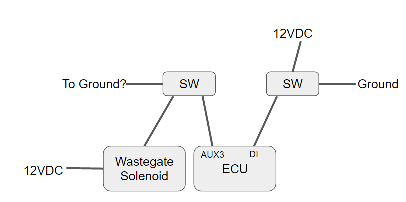
Hello, I recently purchased the G4+ ECU for my MR2. I currently have a boost controller and I would like to retire it in favor of the boost control feature in the G4+ ECU. From reading through the various postings on the forum I gathered that on a 2-wire, 3-port solenoid I would need to connect one wire to switched 12V and the other to the AUX-out port on the ECU. Reading through the manual for the ECU I see that there's AUX3 and it's labeled "Wastegate Solenoid" so I would like to confirm that is the port to connect the other wire on the boost solenoid to. My existing boost controller has three modes, off, low, high and I would like to mimic those modes. I'm thinking that I would need to wire in two separate switches, one to turn on and off the boost solenoid and the other to control low/high mode. Wiring for the on/of switch is pretty straight forward but I'm not so sure about the low/high switch. Again from reading through the forum postings I saw a posting where the recommendation for low/high control is to wire the output pin on the switch to one of the DI ports on the XS wiring harness. So a couple of questions with that approach: 1. What voltage should the input to the DI port be, 5VDC or 12VDC? 2. Programming of the ECU to associate the DI port for how/high mode, not sure where I would start...help!


")