


kielsubaru
-
Posts
10 -
Joined
-
Last visited
Content Type
Profiles
Forums
Events
Gallery
Blogs
Posts posted by kielsubaru
-
-
On 2/15/2019 at 7:47 PM, Adamw said:
So I've spent a bit of time on this over the past couple of weeks and I still can't seem to get it working correctly. The channels that are labelled "EFI EthTemp" and "EFI Eth%" read Baro Press and Battery Voltage like they did originally except they are labelled differently. I'm not sure what else you changed in my configuration.
-
4 hours ago, Adamw said:
Sorry, I must have forgot about this one.
Racepak dont make it easy to receive anything outside of what they decided you want. It is possible to set up a complete user defined stream but it is a major pain in the ass. You cannot do it offline either - you can only change the CAN stuff when connected to a dash.
An easier solution may be to re-purpose a couple of the existing "EFI" channels if there are any that are too important to you. Maybe baro or batt volts?
I had considered changing some of the existing channels, you are correct baro and volts aren't important to me. How do you go about modifying these channels?
Thanks again -
Anyone have any thoughts? I'm pretty new to CAN communications, wouldn't mind some good learning references.
-
23 hours ago, Adamw said:
So are you using the "User configured" CAN in the IQ3? If you attach your ECU and dash config I can take a look.
Under "ECU Type" I set it to Link G4+
-
Hi,
I've installed a Haltech Iq3 Street dash with my Link Thunder, also purchased the CAN adapter harness. I've set it up and RPM, ECT, IAT, AFR etc are all working correctly. I've connected an Ethanol sensor to DI 1, which also shows Fuel Temp. They are reading correctly on my laptop however I can't get these parameters to show up in the Racepak software. Not sure if it's something I've missed in the ECU setup or dash software.
Thanks for your help -
3 hours ago, Adamw said:
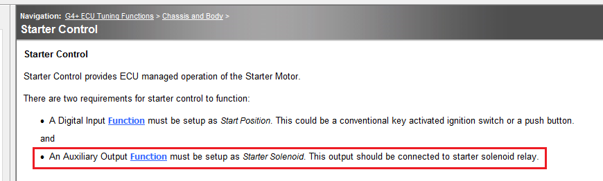
This is only if you want ECU controlled start up. I dont know if your car has "push button start" but if it does it is probably controlled by the BCM, not the ECU.
No push button start on this car, I was intending to use the ecu controlled start as part of the anti-theft setup. But it looks like it isn't going to work how I thought. Doesn't really matter as I can still cut fuel and ignition for anti-theft.
-
5 hours ago, cj said:
This car has push button start right?Assuming its start button, the C32 wire shouldn't be configured as start signal, it should be neutral/park (as per the starter control function which allows park/neutral as a condition of starting). The wiring logic for this input looks to be "clutch+power is in a ready to start state" rather than "car is now cranking", which is what "start" means to the link ECU. You could probably configure this as nothing and just set the starter control to have park/neutral control disabled, because the clutch switch itself is a safety which prevents the starter relay from receiving power when not pressed.as far as where your 3v/7v is coming from... Id guess its a small amount of current coming through the starter solenoid from the c20/aux8 pin. Try pulling the plug on the starter relay and see if it goes away. Assuming you have no other wiring changes in the car, this will confirm whether its current coming via the starter relay.
[edit] just re-read your post and noticed it says "turn the key to on", so somewhere else in the wiring diagram there must be a wire that comes from the key "start" position into the ECU. Set this as your start position, and either set the C32 pin to p/n as above or disabled. As far as the ECU is concerned though you need to treat it a bit like a push button start as the ECU is apparently controlling the starter rather than the key position doing it directly.[edit #2]... I missed the (ST) at the top of those 2 wires.... those are both only fed 12v when the key is in the start position, so you had it right all along that C32 is the START position. I still think the voltage you are seeing is an artefact of pin C20 sitting high when "off". Try taking this wire out of the ECU and grounding it to the chassis instead. This will mean the ECU itself cant prevent cranking, but means you dont have a weird loop going on between an aux out and an input.
Looks like you nailed it, disconnected C20/Aux. 8, the 3v/7v volt disappeared from C32. Grounded C20, and now it behaves exactly as it should. 12v on C32 with the key to START.
Looking at the diagram again, I see there is no purpose having C20 connected to the ECU, it may as well always be grounded. I only connected it to an Aux. output because that's how the OEM ECU was and also when looking through the Link manual it says to do it in the starter control section.
Thanks for your help, I owe you one

-
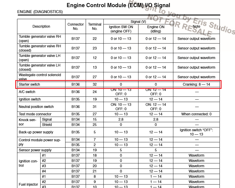
Fuse No. 21 only delivers 12v when the key is turned to start, referring to my service manual, pin 32 is the "Starter Switch". What I don't understand is how I've ended up with 3v on that wire with the key off. I haven't modified the factory harness, rechecked my patch harness wiring, nothing has shorted. I find it odd how DI10 turns on and off rapidly while the key is ON. Thanks for your response.
-
First time poster here,
Bit of background, I've installed a Link Thunder on my 2007 Subaru Liberty GT Spec B Manual with a built EJ255. I haven't cut the factory loom, instead made my own patch harness. I've had no trouble setting up the ecu, apart from the Start Position which I have assigned to DI10. I've got a problem where with the key OFF I have 3v on this wire, 7v with the key ON and 9v while cranking. I'll attach a link to a video which shows DI10 and Aux. 8 (Starter Solenoid) are flashing on and off rapidly with the key in the ON position. One I turn the key to start they both stay ON, release the key and they flash again.
https://www.youtube.com/watch?v=UWuCVqM-828
I've plugged my OEM ecu back in and tested the voltage, 0v with the key OFF and ON, 10-11v while cranking, which I believe is correct.I've also attached a photo of the OEM wiring diagram for reference, I've connected pin C32 to DI10 (Start Position), the "On Level" set to HIGH. Then C20 to Aux. 8 (Starter Solenoid), the "Polarity" set to LOW.
I'm trying to work out if I have a wiring problem or if I may of configured something wrong. I can provide any other details, any assistance would be great.


Racepak iq3 with Thunder
in G4+
Posted
Thanks Adam, I loaded that in now it's working perfectly. I'm still getting my head around setting up CAN communications, is there any good articles worth reading?