


Bram
-
Posts
37 -
Joined
-
Last visited
Content Type
Profiles
Forums
Events
Gallery
Blogs
Posts posted by Bram
-
-
Hello.
Please excuse if this has been covered or in the wrong section.
I am wanting to buy 100m rolls of the type of electrical cable used on the Link pre-wired ECU plugs. I am an auto electrician and I do vehicle re-wires and want a good source for that type of wire to purchase in bulk. Most of the cable available through the auto electrical wholesales i deal with are "auto" cable. Which is very thick and bulky, and doesnt come in thinner sizings. And is far from ideal.
I would like to know the brand and series of cable that link uses, as it looks right for what i need. And a place to buy decent quantity. Eg digikey, rs online, mouser or similar probably have it, but i would like to know which type it is as there is so many to choose from. Or if anyone knows similar/better cable for purpose.
Thanks in advance.
-
Keen to hear which shop it was? Im also in WA. I bought my ECU through BYE and the cable was included. They even called me up when the car was going on the dyno so i could come down and watch/help.
-
I have a big hydro handbrake in the car. So would def need to unload the diff when i yank that.

-
And its not like your are gonna be stealing potential customers away from DCCD-Pro by making the ECU handle control from it. Most people that want DCCD will still just get the controller rather than going for a full stand alone ECU system.
But doing it via the ECU will allow people with the ECUs already, the possibilty to streamline thier instal with one less extra module. And people who are looking to go stand alone ECU may choose Link over others for the added ability to handle DCCD.
Having access to manipulate the way the DCCD interacts can be very interesting. DCCD makes a massive difference to the performance of the car on tighter/twisty stuff like tarmac rallying. I know from my own experience racing and forgetting to turn the DCCD on, it can mean as much as 2-3 seconds per minute of racing VS with it on (I turn it off in the back staging/carparks as the diff bind is annoying.) So having the ability to fine tune further could still mean big performance advantages over a non adjustable setup.
-
Ok. Thanks for the reply.
And im happy to do some testing etc. I can measure current draw over the DCCD coil when energised. And any other tests that may need to be done.
I know there is probably some copyright infringements looming when i say this. But it may also be good to look at how the DCCD-Pro brand of controller functions. These would probably be one of the most common controllers used in the Subaru world for people like me who retrofit a DCCD box into a NON-DCCD vehicles. As you know Subarus are like Lego and you can pretty much put anything Subaru into anything else Subaru. So DCCD retro-fits are extensively common for non STi vehicles like WRX, Liberty, Forester and so on. I could perhaps hypothetically hook my DCCD controller back up, and then connect it into the Thunder to log its output.
-
I have no idea on how possible this even is, or how sort after the feature would be, but im gonna throw it out there anyways as it is something I would like. And I can potentially see it being useful for tarmac rally, gravel rally, and even circuit cars. (Subarus, and possibly Evos/GTRs )
I would like to be able to run DCCD via the ECU. I have a Thunder ECU and '07 STi DCCD 6spd gearbox, retro-fitted into a non-DCCD equipped Subaru.
In order to utilise the DCCD I run a DCCD-Pro controller as my car was never equipped with the OEM control system. The controller would seem pretty basic in that it only monitors TPS, lateral/accell G-force and a handbrake switch. And then has some user inputs, which is basically a trim pot knob/wheel for how aggressive it is and an auto button.
Given that the Thunder has accelerometers built in, it could potentially have access to all the inputs needed for calculating the DCCD, plus many many more. For example individual wheel speeds or brake switch inputs.
As for output, AFAIK, the Subaru DCCD is basically just driving a electromagnetic coil in the gearbox. I dont know how much current is used, but im guessing perhaps a E-throttle channel could be used to drive it? They can do 4 amps correct? Thunder has 2 E-throttles. So even on cars that use the first E-throttle as an E -throttle, there is still the second spare.
Now i know most of the Subarus will probably just have a plug-in ECU. Which is Xtreme isnt it? So they only have 1 E-throttle, which if the car is using it, no good. But the earlier models with cable throttle could potentially use the E-throttle output still, even if using a plug-in?
And im guessing it could also be applied to EVOs aswell with thier ACD system. Which is AFAIK a pump and solenoid. So possibly easy enough to make work?
I know you guys prioritise new features by how usefull the feature would be to the customers (and how much hard work it is for you to implement), and I understand its probably not gonna happen due to how many people would use it and how much programming it is for you to do. Im just putting it out there.
-
Thankyou.
Im sure i searched the PC-Link help file. But i didnt see that anywhere. But, yes, that looks like a needed piece of info.
Still a fair ways off doing that step yet. Im doing a top to bottom re-wire of the entire car. (KE20 Corolla) So all body electrics, plus complete wire in of the engine management. Every OEM Nissan connector was sourced from EFI Hardware for the SR20, so no cut and splicing on the engine wiring, i can terminate directly into the OEM components. 1NZ Yaris COPs. Large circular bulkhead connector for the engine wiring pass-through into the cabin. And everything is top notch components. ETFE wires, harness-flex conduiting, dual-wall shrink, Deutsch connectors throughout - Every size DT, DTM, DTP, DTHD, HD30.
Every harness can be unplugged and removed if need be. Im about 75 hours into it now. And realistically thats about 3/4s of the way there. Im full qualified auto sparky. But this is only the second Link ECU ive wired in. My Subaru being the first.
-
Appreciate it mate.
I was gonna presume that be the case. But may aswell ask before i terminate the wire/pin into the plug.
-
Hello.
Another silly SR20 question.
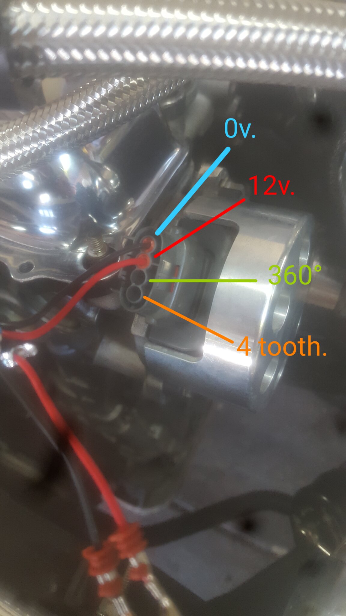
With the crank posistiin sensor on the side of the cylinder head. It has 4 wires. I know which when looking into the plug.
1st pin is 0v -.
2nd pin s Ign 12v +.
3rd pin is 360° tooth.
4th pin is 4 tooth.
Q. Which do I use as trigger 1 and trigger 2 on the Link ECU?
(Forgive the newb question. Im sure this has been covered one billion tomes before. But i couldnt find anything specific to the way the link ecu works with a quick search through the net or on the forums. So though it easier to ask.)
-
Sorry. Just to clarify.
Can you please tell me which is which from looking at this photo?
-
Thanks for the advice. Appreciate it.
-
Hello.
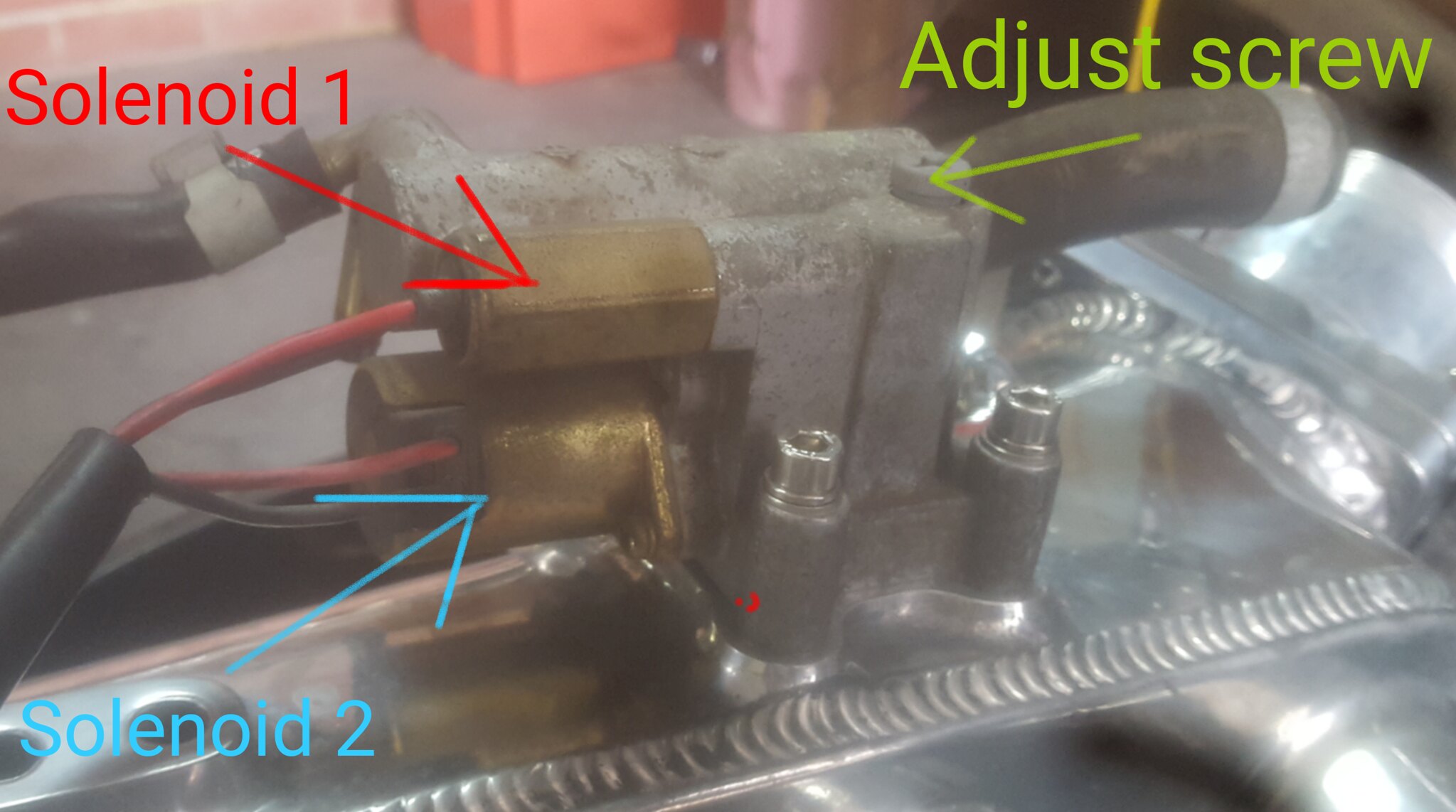
Im wiring an S13 SR20 into a KE20 Corolla using a Fury G4+. Making new wiring from scratch for both the vehicle and the engine. Just want to confirm wiring to the idle speed solenoids. I'm a Subaru nut and not 100% familiar with the Nissan system. But it appears there is 2 solenoids - Both terminate into a 4 pin plug. One larger than the other.
Will the ECU need to switch both solenoids individually on a separate AUX OUT channel?
I presume I wire one side of each solenoid to a 12v IGN+, and the other side each to its own AUX OUT on the ECU? Is this typical for a Link install?
And can someone give me a reason why they appear to have used 2 separate solenoids? I'm guessing one is the actual idle speed control, and maybe the other is a coarse adjustment for times of high load? (A/C or something) Or maybe one is like some type of emissions purge? I have no idea as the existing wiring is butchered with the original engine conversion, and the hose plumbing is all apart as the car has been receiving alot of other fab work and TLC before it came to me for wiring?
Ive tried uploading a picture, but was unable to make it work?
Thanks guys.
-
Thanks
-
It seems I cannot use a spare injection channel to run FP Speed. It would seem it will ONLY run in Aux Outs that do PWM. But its OK. I have shuffled around a bunch out outputs and have got pretty much everything I wanted on a channel.
Please find attached my ECU map as requested. I have edited it a bit since the original problem. But Im pretty sure it would still fault if i tried again. Also I would greatly appreciate it if you would look it over and tell me if you think it would be ok to try and start the engine on. I havent attempted running the engine yet. But hopefully try it this weekend. I just want to be able to start the engine up and check for oil/coolant leaks etc and then it will be taken to my tuner who will tune it proper on a dyno. I would atleast like to be able to start the engine before taking it there. I basically copied over the LINK base map for a Subaru and edited it to match what I have.
Also. On a side note. Why is it not possible to re-name Aux outputs above Aux 8. For example I can re-name Aux out 8. But I cannot re-name Aux 9. I would like to run a few more GP outputs, and naming them would make it a little easier to keep track of.
-
Are you sure about using an unused injection channel for FP speed? I cant get it to work on injection out.
I will get an upload this evening. although i have changed it slightly since the problem occurred.
-
Can i use an unused injection output to run the fuel pump speed. (to run Subaru OEM controller?)
-
What firmware and PC link version are you running?
ECU firmware 5.6.4.3240
PC Link Version 5.6.4.3229
Before I started moving the FP speed output around i did check the help file manual, and supposedly any output is listed as green for go. But it wasnt until i double checked the paper pamphlet that came with the ECU that it apparently only does PWM on 1-8 output channels. Only reason I wanted to change it around was to use an output for speedo out so i can use the internal multiplier to adjust my speedo to suit different tyres. (and have the start up sweep match my tacho aswell.)
-
Im pretty sure its the latest. i will double check when i next go out and work on the car. it was getting late last night and i figured it best to stop and start fresh another time.
I looked in the help files before i tried it (moving the fp speed around) and im sure that there is a chart that says which output can be used for which function. And im sure all boxes for FP speed were green across all outputs. But when i looked in the little pamphlet that came with the ECU it says some that only the lower number AUX outputs support PWM. And the higher ones dont. I did try quickly putting the FP speed back to a lower AUX out channel and the ECU didnt crash. So im assuming that was the cause.
It would be nice if the PC link didnt let you be able to select an AUX out that is incompattible with the function. EG FP Speed needing a PWM capable AUX out, Instead of allowing the error, then crashing.
-
Hang on. i think its because im trying to select on an AUX output that doesnt support PWM.
Derp. feel like a tard.
-
Hello.
My G4+ Thunder is doing some very weird things? It seems to be tied into FP Speed in AUX outputs? It seems the ECU will crash as soon as FP speed is enabled to an output. It doesnt seem to matter which output either. Like a software glitch or something. I have tried restoring ECU to factory, then reloading the MAP. The ECU seems fine, but as soon as you touch the FP speed setting the ECU disconnects from the PC, and seems to hang. It keeps the main relay alive when its doing this aswell. If you try and connect while its in this state, you get an error message stating "Error: ECU has had an exception and cannot connect. Do you wish to view the debug information?" The data from debug information is below. Once it crashs like that, the only way to get it back is to pull the main relay or disconnect the battery. I have tried Un-pinning the wire that im attempting to assign to FP speed entirely from the ECU and the try, and it still crashs everytime. HELP?
Error: ECU has had an exception and cannot connect.
Please email the following information to [email protected]Trap!
TFR=0x0002
Rv=0x0CA8
SP=0xFB92
CSP=0x0005
C=0
Regs=
R0=0x0050
R1=0x9D4C
R2=0x0006
R3=0x58F2
R4=0x0024
R5=0x0000
R6=0x0000
R7=0x3500
R8=0x2446
R9=0xC01A
RA=0x0023
RB=0x0000
RC=0x0000
RD=0x5505
RE=0x0000
RF=0x0084
Stack=
0x5505
0x0002
0x1801
0x9922
0x8EAA
0x7EBC
0xB204
0x0002
0x0E9E
0x0002
0xA8DE
0x0003
0x0001
0xE24D
0xE23C
0x2446
0x0001
0x2446
0xA170
0xA0FA
0x599C
0x0002
0xFC00
0x000C
0x0000
0x0000
0x4BE0
0x0005
0x0005
0x7578
0x0005
0x0801
0x0004
0x0900
0x0006
0xF3DE
0x0005
0x1834
0x0005 -
Cool. All under control. Both sensors are Honeywell. Fuel is the Stainless steel PX2 0-100psi. And the oil is a brass PX3 0-10bar. Both are refferenced against atmospheric pressure (gauge). Only got the one stainless steel sensor because they are over double the price of the brass models.
Calibration for them is easy. Linear 0.5 to 4.5v which equates exactly to the sensors specified range. 0-100psig or 0-10bar.
-
Although it may be possible to calibrate your sensors in absolute I cant see why you would ever want to? Assuming this is a car and not a spaceship...
If you look at your oil pressure in a log for instance you dont want to be mentally subtracting atmosphere from it every time. You really only need absolute pressure for MAP or EMAP to calculate density, any other pressure measurement I can think of on a car should be gauge pressure.
Yeah. I totoally get that. As you say there is no need to measure absolute for those 2 parameters. And i dont think id ever see oil or fuel in vacuum either (which my sensors are unable to measure). I just wanted to know which way to set the cal table so the value represented in the ECU matches the actual pressure.
For example, IF the ECU did measure fuel/oil in absolute, I would then have to add an approximated 1 atmosphere (101kpa) onto my scaling values listed by by sensor manufacturer.
BTW - My car is a spaceship...
-
Hello again.
Just another silly question. When calibrating an oil pressure sensor to the Link G4+. Does the ECU use absolute or guage readings? The sensor manufacturer has specified the sensor refferenced to atmospheric pressure. So that means its range is effectively 1-11bar absolute or 0-10bar above barometric pressure. What way of measurement is the ECU looking for? I would assume everything be in absolutes, but it doesnt look right for oil pressure.
And I also have a fuel pressure sensor. Fuel pressure sensor is from the same manufacturer (Honeywell) but it is 0-100psi again as a guage reading. Same question as the above, which measurement is the ECU looking for?
Im sure this has been covered somewhere before. but i couldnt see it with a quick search.
-
Thanks for the replies. I might try and do it that way, except use oil pressure as the main trigger for engine running (trigger 3). Looking at the way Scott has suggested, it looks like the Scavenge pump trigger 1 + 2 means it will only start to run on timer once its already been running. (from first being triggered by trigger 3 - engine RPM greater than 10.)
The reason i would maybe look at using oil pressure sensor input instead of RPM is i have a oil accumulator/accusump fitted. So there would be potential for that to be discharged, and the engine not actually started (pre-oil but then no start). And although i highly doubt the small percentage of oil that would make it through the turbo VS whats discharged to the rest of the system from the accusump would be enough to fill my turbo oil drain collector, i guess it still would be nice to drain it. And hearing the pump run would also hopefully remind me that i have just discharged the oil accumulator.

Where to buy cable.
in G4+
Posted
Thanks for the reply Adam.