


Markus
-
Posts
14 -
Joined
-
Last visited
Content Type
Profiles
Forums
Events
Gallery
Blogs
Posts posted by Markus
-
-
Hi
My friend just switched from the G4+ to the G4X . We set the CAN stream to the Link Generic , that we also used on his G4+
However , the output is different on the G4X and not like inGeneric Dash.lcs the description
Here is the Output versus the Displayed values in the Software . In General it only seems to convert integegers to HEX (So no Conversion from RAW neccesary and values are rounded )
In the Description of the protocol in the G4x helpfile the protocol has not changed compared to the G4+.
But i see for instance the temperatures should have a offset of -50 as they are sent as unsigned integers
ECT is shown in the software with 23 degrees so i would expect 0x4300 which is 73 dec , but i am receiving 0x1700 which is 23 dec .
The same behaviour seems to be with all the Temps

Here is the CAN Data i receive :
(1591528882.121744) can0 3E8#0000000065000000
(1591528882.121855) can0 3E8#0100660004000000
(1591528882.121974) can0 3E8#0200000000001700 // ECT is sent without the offset so only positive numbers are possible
(1591528882.122098) can0 3E8#030015000B000000 //Battery voltage should be 11.97V but i only receive a value of 11 dec = 0x0B00 instead of 1197 dec
(1591528882.122223) can0 3E8#0400000000000000
(1591528882.122352) can0 3E8#0500000000000000
(1591528882.122474) can0 3E8#0600000000000000
(1591528882.122596) can0 3E8#0700000000000E00
(1591528882.122721) can0 3E8#0800000001000000
(1591528882.122846) can0 3E8#0900000000000000
(1591528882.122978) can0 3E8#0A00000000000000
(1591528882.123097) can0 3E8#0B00000000000000
(1591528882.123224) can0 3E8#0C00000000000000
(1591528882.123347) can0 3E8#0D00510000000000Could you please clarify if this is a bug , or did i set up something incorrect ?
Kind Regards
Markus
-
Thank you for the input . I think i will stay with 4 wheel inputs then and sacrifice my 2nd can bus
DI1 Traction control Button
DI2 Ethanol Sensor
DI3 AC request button
DI4 L/F wheel speed
DI5 R/F wheel speed
DI6 L/R wheel speed
DI7 R/R wheel speed
DI8 Clutch switch
DI9 Start pos
DI10 Power Steering
I read a couple of threads where people use a rotary switch with different resistances to switch between different traction profiles via AN Volt input ( exactly what i am planning to do ) but it seems the traction control on/off has to be assigned directly to a DI via a virtual aux correct ? Is there a specific reason that i require a DI for the traction control on off switch and can't use a AN input with a rotary switch and some resistors directly ?
-
I have a question regarding traction control on a G4 Fury.
Is there any benefit running 4 wheel speed inputs compared to just 2 ( one front one rear ) ?
I am still in the process of wiring and i am running out of digitial inputs (and i don't want to scrifice the can2 for additional digital inputs ) , hence my question .
The car in question is a Rx7 Series 6 .
-
6 minutes ago, Brad Burnett said:
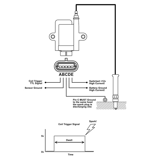
@Markus just curious what software you used to make your wiring diagram?
Microsoft paint and lots of patience :-)
4 hours ago, Adamw said:Either usually works, but sensor ground is preferable for the signal ground on these coils. The signal input on these is TTL logic level so you only need a 0.8V ground offset and you can get a random sparks. It would still be unlikely in normal circumstances to have an offset of 0.8v between cyl head and ECU ground but better to be safe than sorry.
I will add that it is fine to connect both the crank sensor grounds and the shield to the same shield/gnd pin. This is how its done in the Link supplied looms. The "Shield/gnd" pins and the "ground out" pins are connected internally and can be used interchangeably.
Edit: I just noticed a couple of other mistakes:
Boost solenoid needs switched +12V on one side, ECU aux on the other (cant high side drive a boost solenoid).
The pressure sensor pinouts look wrong, usually the center pin is the signal.
 I made the sugested changes . So i understand you correct that on the AEM coils i was right to use Sensor Ground ( As this was what AEM's diagram indicates )
My last question is with regards to the FAN relais . The Rx7 has 4 Fan relais from what i can gather i am unsure to which one i have to connect it . I want to use INj7 to switch on the fan do you have maybe any drawing of the Rx7 FD Fan wiring ?
-
So I put the wheel speeds via ABS sensors aside for now .
I don't have a OMP or Aircon
But i will have a RX8 DBW Throttle and Pedal as well as AEM Smart coils and dual fuel pumps . I made a mockup diagram and wanted to know if that looks correct ?

-
So i have received my G4 Fury which i will start to wire up this weekend into my RX7 FD3S Series 6 .
I was planning to use the 4 ABS sensors as wheel speed sensors do do traction control via E-Throttle with a RX8 Pedal and RX8 Throttle body .
So here are my questions :
1. Can i just splice into the ABS Sensors (as i plan to still use the ABS) ?
2. Can someone tell me the Link settings for the RX7 Series 6 ABS Sensors
3.Can i Run also a 5th speed input ( OEM gearbox sensor ) for general speed
(this is the speed i want to ouput as vehicle speed on can for my dash )
-
I have been able to sucsessful add extra parameters with new frames to the Generic LInk CAN protocol
The Link protocol displays Lambda on the Generic CAN Protocol .
I would like to add a additional source to display A/F ratio ( i prefer AF to Lambda) . But i am not sure which one is the correct Parameter .
-
thank you :-)
-
I am trying to figure out which Pins on the PCB CAN/RS232 are CAN high and CAN low but i could not find the info anywhere in the help files .
Could someone point out CAN High and CAN Low for me on the connector

-
I am trying to do the same for a friend of mine , is it possible to get more info on the CAN ID's and conversions for the MicroTech Automotive CAN Protocol Version 2.0 ?
-
Thank you very much for the Awesome and fast Tech support :-)
This was the exact info i needed
Kind Regards
Markus
-
Thanks for clarifying that . That was a good explanation .My Device is a Raspberry pi with CAN BUS hat and a Touch screen which runs my own programmed software and is used as a Datalogger as well as a Graphical Dashboard . I have already implemented The Haltech V2 as well as the Adaptronic Protocol in my device , so i wanted to make a CAN configuration file for the Link to output the data in either the Haltech or Adaptronic Format as i already implemented those in the software .
So just for a final clarification for my use case i would define my 6 channels one per ID and leave the Offset always on 0
-
Hi I am new to the forum
I would like to configure the CAN output format but i have still a few questions
The output format i want to create is 11-BIT identifier + 8 Bytes payload
All bits are 16 Bit Signed integer values in BIg Endian format
I would like to define CAN ID's from 0x300 onwards to be output
What i have so far is in the first tab "CAN Setup Mode":
CAN Module :CAN1 Mode: User Defined Bit Rate 1 MBits/s
Channel 1 Transmit User Stream1 CAN ID 300 Format :Normal
This seems all still very clear to me (my assumption is that ID300 is just the Start adress right ?)
Now when i define the frames :
Lets say Frame 1 would be for ID300
Parameter Start Width Byte order Type Divider Multiplier Offset
Parameter 1 0 16 MS First Signed 1 1 0
Parameter 2 16 16 MS First Signed 1 1 0
Parameter 3 32 16 MS First Signed 1 1 0
Parameter 4 48 16 MS First Signed 1 1 0
How would i make Frame two to be at ID 310 for instance , do i just change the offset ?
Is my understanding correct that Offset is decimal ? so Decimal 16 = Hex 10 therefore offset 16 = ID310 ?
ID 310
Parameter Start Width Byte order Type Divider Multiplier Offset
Parameter 1 0 16 MS First Signed 1 1 16
Parameter 2 16 16 MS First Signed 1 1 16
Parameter 3 32 16 MS First Signed 1 1 16
Parameter 4 48 16 MS First Signed 1 1 16
Am i correct with this assumtion ?


CAN Stream behaviour issue on G4x
in G4x
Posted
Thanks for the quick reply , that clarifies it .
I used the Ics file that was included in the G4+ folder for the Generic dash and just added Ethanol % to it .
I will modify the lcs file accordingly for the G4X .
Many Thanks for your fantastic support