Beams AE82
-
Posts
46 -
Joined
-
Last visited
Content Type
Profiles
Forums
Events
Gallery
Blogs
Everything posted by Beams AE82
-
Hello Adam. I do not yet have a sensor in place but but i have identified a position where I can mount a hall effect sensor on 1 of the rear non-driven wheels. I will try source a unit this week that will fit in the space available and hopefully fit and wire it in over the weekend. I will assign it to DI1 as ground speed. Please go ahead and share with me your suggestion.
-
Hello Adam. Thank you for your response. Ok, so we'll eliminate option 3 then. I'd like to play around as an interim measure and to learn the timer functionality with option 1. I'd like to follow the following sequence of activation events, thereafter, maybe you can guide me through the timer setup. Dash mount enable switch made. Clutch mount enable switch (in series with Dash switch) made - clutch depressed. TPS >90% RPM limit activated. When I release the clutch -clutch switch input will be broken, I want the timer to start and run for "X" time period, extending the launch control rpm limit turn off point by that period. Effectively I guess this acts as a delay timer in industrial automation terms. Please guide me through this setup process. For Option 2, I will source and install an appropriate Hall effect sensor on one of the non-driven wheels. I'm running drum brakes on these wheels so space/fitment might be an issue but I will make a plan. Ideally, the sensor should pick up from a bladed wheel or even from an array of evenly spaced bolt heads I guess. If I drilled say 4 evenly spaced holes into the rim of the brake drum, would we be able to configure the brake in the signal as the "gap/hole" passes the sensor as our input? Could you possibly share some setup guidelines to configure this concept in VTS? I'd still like a digital enable switch for the function, in my case the Dash mount toggle. What sort of a control table would I set up for this? 2D with Road speed on 1 axis and RPM limit as the variable input data as per simple example below or would there be benefit to adding TPS as another axis against road speed in a 3D table? 3D example Road speed TPS 0 10% 20% 30% 40% 50% 60% 70% 80% 90% 100% 10 0 0 0 0 0 0 5000 4500 3700 3000 20 0 0 0 0 0 0 5500 4800 3700 3000 30 0 0 0 0 0 0 6000 5200 4000 3500 40 0 0 0 0 0 0 7000 6200 5500 5000 50 0 0 0 0 0 0 8000 7700 7300 7000 60 0 0 0 0 0 0 8000 8000 8000 8000 2D example Road speed 0 10 20 30 40 50 60 RPM Limit 0 3000 3000 4000 5000 6500 8000
-
Hi all. Firstly, big ups to all the assistance you guys have provided me with over the last few weeks. I am progressively building on my tune, logging real time and using Mixture map almost exclusively now for the fuel tuning. My injector duty cycle has peaked at 80% during yesterdays tuning session indicating I'm probably close to my initial target 150kW. (Spec is 1987 Toyota Corolla EE80 FWD, 3SGE Gen4 and C60 6sp gearbox with LSD). Onto todays topic of discussion. I'd like to setup an effective launch control. Despite running an LSD, there is no way I can put the power down on hard pull aways. Traction or lack thereof is a very real problem for me. My Launch control is currently activated as follows; Dash mount enable switch made, clutch switch made for 1,5sec, >90% TPS and it then launch control function limits engine speed to 4000rpm. As soon as I drop the clutch all hell breaks loose and traction is again lost. Not a good solution.. I have some thoughts to improve the setup, as follows ; 1) Add a timer which will hold launch control active for a set period after I release the clutch. This would enable me to get moving before releasing the full RPM range of the engine. This could work all be it a rather rudimentary solution. I'm not sure how I will add a timer as I still need to look for a method in the software. 2) Though not necessarily a quick easy solution would be to add a wheel speed sensor to a rear non-driven wheel. I could then run a varied RPM limiter against wheel/road speed input. Activate via dash enable switch, >90% TPS and look for non-driven wheel speed input between 0-60km/hr speed range for example. After 60km/hr I'd be into 2nd gear where lack of traction is less of a problem and "Launch Control" would no longer be active. 3) Another option would be to run a basic version of "traction control" by % slip calculation (between front and rear wheels). This would necessitate the addition of at least 1 front and 1 rear wheel speed sensor. Then span % slip against a "soft" rpm limit. As traction is found the "limiter" would not longer be in place. Another query, is there a preferred type of wheel speed sensor that I should source and what is the recommended frequency range I should aim at? At a very enthusiastic and safely over estimated top speed (rpm limit) in top gear (8200 rpm, 250km/hr in 6th gear), my wheel speed will be 2301rpm. Please share your thoughts on the above. All suggestions are welcome and will be greatly appreciated.
-
As always, thank you for the prompt responses gentlemen. I have never worked with an ECU before that is backed by such manufacturer support. You guys are legends. Simon, I am running the last update of VTS in my V88. Fuel equations available are MAP, BAP and MAP/BAP. I am running TPS as my load input so fuel Equation is selected is MAP as I will run a wilder engine specification in future - longer duration cams and head work. I figured to rather develop my map from now using TPS as load than very likely have to change to it after engine developments in future. Adam, master fuel was 10 so I changed to 13 and adjusted fuel table by 1.3333. Looks much better thank you with cell values around 55 to 60 mid map now. Once the rest of the household wake up I'll perform a store, start up and confirm all in order. On another topic. As I am running a V88, am I correct in stating that it does not support the Launch control function and that I should create a % Slip calculation table for this purpose? I have wired in a digital input - enabling toggle switch - and will wire in a second in-series clutch switch soon to activate "launch control". I still need to Install wheel speed sensors.. Thanks again for the help.
-
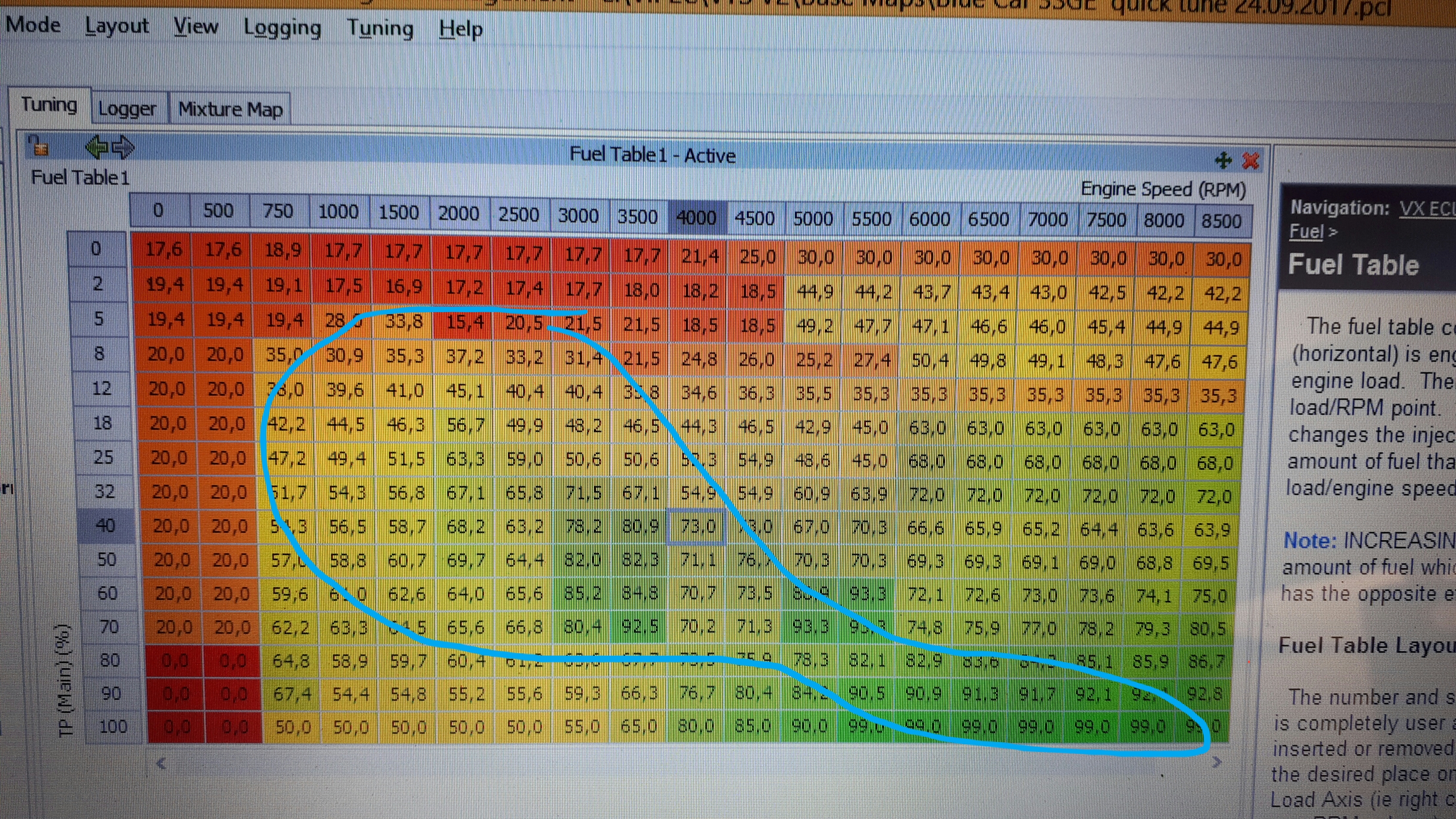
Hi all. So, trigger issues were sorted earlier this week and first start up checks proved all good. Setup is 3SGE Gen4 fitted to Toyota EE80 Corolla with C60 6sp gearbox and LSD. I drove the car today for the firat time and ran Quick tune to start building the fuel map. All good barring that my values in the center of the map are well above the guideline 50 and quickly maxed out at 99.0 from 100% TPS, 5500rpm onward. Mid map values are around 80. Is there a way to adjust the Master Fuel value and bring the map values down, but retain the fueling I have developed this far? Edit. I've added an image of my fuel map in its current state of infancy. The blue border surrounds the cells roughly tuned this far.

-
Base timing set and engine started up immediately this morning! Oil pressure, fuel pressure, oil and water temp all good. Thanks again to all who have assisted me thus far. Once I've competed the exhaust cold end I'll be ready to start road tuning. Hopefully before the end of the weekend.


-
Hello again Adam. Upon my return to town last evening, I ran a continuity check again on my trigger signal wiring. All was in order despite my incorrect diagnosis earlier this week. I proceeded to disconnect the Crank angle sensor and then connected a spare sensor. This sensor was in OE configuration with the shield not linked to the negative wire. After powering up, I passed a screwdriver over this sensor and immediately had signal reflecting on the Runtimes page. I then opened up the original sensor wiring at the sensor end and broke my connection of the shield wiring to ground wire as discussed previously. Now, when cranking the engine I have a signal and rpm count. Next I need to set my ignition base timing and will attempt a start up thereafter. Thanks again for all the willing assistance.
-
Hi Adam. There is no signal input visible on the run time page. I did a check on my signal wiring and it appears there is a problem between my firewall plug and ecu plug. There is no continuity on the red trigger wire. I'm out of town this week and only back home over the weekend. Will sort out the wiring issue then and keep you posted on progress. Thanks for the assistance this far.
-
Good morning all. After correcting my VVT wiring I was eventually ready to crank The engine over for the first time. I have noticed that there is no crank angle sensor signal coming to the ecu and this no Tacho signal output iether. After running through the wiring diagrams in the help files I may have found 1 issue. The help files suggest to connect the shield to tje ground wire at the ecu end of the cable. I have connected the shield to the ground wire atvthe sensor end as well. Could this cause any issues? I have also noticed that there is continuity between the sensor ground and chassis ground terminals when checking via the harness. Is this correct? My configuration for Trigger setup is as per thehelp files 3SGE Beams guidelines.
-
Ok, I now follow, thank you David. I have assigned Aux 3 per recommendation in the help files and as you have suggested above. I will now route a power supply from my ECU power up relay to the + terminal of the solenoid so that power is only supplied at Ignition ON. Thanks a mil for the quick responses and help gents, much appreciated!
-
Thank you for your responses gentlemen. I may not have been clear with regards the description of my current variable timing setup, sorry. The camshaft timing control is continually variable - VVTi and not ON/OFF switched control. A PWM output is required to control the solenoid. This I have configured within my start up file, based upon the SXE-10 startup file in the VTS software as well as the file in the PC Link software. The solenoid or rather OCV (Oil Control Valve) per Toyota description, has a 2 pin connector. One is assigned to a suitable PWM enabled Auxiliary output and the other needs to be connected - to sensor ground, I think. This is what I require clarity on please. I am unfortunately not near a PC with VTS loaded otherwise I'd share a screenshot of my config including VVT setup for further clarity.
-
Good morning all. I hope that someone will be provide me with some assistance. I have completed the mechanical elements of my Corolla EE80 FWD / 3SGE Gen4 Beams build and am currently busy wiring in my V88 ECU. Could someone possibly confirm the Inlet VVT solenoid wiring for me? As I understand, the + terminal wires into an assigned Auxiliary Input, in my case no.3. The - terminal should go to sensor ground. For one or other reason I am doubting this.. I hope someone will be able to clarify for me. Robin
-
Hi Peter. I will start wiring up my Beams engine transplant soon. What was the colour of the crank angle sensor + and - wires? I'd like to avoid any possibility of a similar issue to what you experienced. Also, how did you connect the coaxial shield? Did you end up using MAP or BAP and with what outcomes? Have you used TPS or MAP for fuel and ignition maps? I am aldo leaning toward BAP/TPS load as my setup is much like yours, also running ITBs. Rob
-
Hi Dave. Wow, late response from my side, sorry. I'm based in Port Elizabeth, RSA but have been I Europe for the past few weeks. 2 to go and then i return home. Thanks a mil for your valuable input. I'd really appreciate it if you could share your map with me. more than anything I'd like to familiarise myself with the basic setup parameters you have chosen. Are you running plenum and single throttle body or individual throttle bodies? Cheers, Rob
-
Hey Mgtezza. Did you find a suitable base map and would you possibly mind sharing it? Are you running MAP and or TPS as your load input? Rob
-
Hi all. I am making progress with my build and conversion. My basic engine setup is a Single VVT 3SGE Beams engine. It will run 4age 45mm individual Throttle bodies, individual coil on plug setup per original fitment and I plan to control the Intake cam and monitor and control Knock and wideband AFR. I will do some headwork, change cams and run slightly higher compression ratio. I have a Vipec V88 ECU that will be used to run the engine. Does anyone have a base map for the single VVT, or dual VVT blacktop engines that they can share with me? It would be super to be able to start off with a Map intended for an ITB setup on this motor. Cheers, Rob
-
Vipec V88 versus Link Storm for 3SGE Beams
Beams AE82 replied to Beams AE82's topic in ViPEC V Series
Hello Scott. Thanks again for the very informative response. I do have the OE knock sensor as well as a donut type Bosch unit. When it comes to installation time I will make a decision on which to use. The travel I refer is work related so time away from home, and no race car progress! Keep well. Rob -
Vipec V88 versus Link Storm for 3SGE Beams
Beams AE82 replied to Beams AE82's topic in ViPEC V Series
Hi Scott. Yes, mine is the Caldina ST215 engine. I have purchased the V88. I've downloaded the last revision tuning software and thus far it appears to work with Windows 8.1. I will only wire up and install in a couple of months as I have quite a bit of travel coming up. Nearer the time I'll be sure to call on you guys for guidance. I do have a few more questions for now. Should I want to run an ethanol /petrol mix for drag use, would the ecu, with an ethanol sensor connected, be able to automatically trim the fuel map to suit if I simply drain the fuel and fill the tank with ethanol/petrol mix? Which ethanol sensor do you recommend? Which knock sensor do you recommend I use? I have a Zeitronix ZT2 wideband logger. Will it's 0-5v analogue output be a suitable input to the v88 for wideband closed loop tuning? I expect it should be fine. Once again, thanks a mil for your input and guidance thus far. Much appreciated. Rob -
Vipec V88 versus Link Storm for 3SGE Beams
Beams AE82 replied to Beams AE82's topic in ViPEC V Series
Thank you for your responses gentlemen. I was referring to G4+ (Black housing) but what was not accurately accounted for is the current foreign exchange rate and shipping / customs duties. The revised pricing I have received places the V88 cheaper by quite a margin. Additional inputs and outputs are always a big plus and although possibly not on this build, I may require E-Throttle control should I run the Blacktop 3sge plenum / single throttle body intake setup in future. I suspect the V88 may be the good option. Are there base/starting maps available for the 3sge Beams motors? What version of windows is required to run the Vipec software? Will it run on Windows 8.1 or 10 or only 7 and prior? Thanks again for your responses. Rob -
Hi all. I'm new to the forum and hope that someone will be able to guide me. I am currently busy with an AE82 / 3SGE single VVTI Beams build for track use. Engine control wise, I would like to be able to monitor knock, Lambda and Control the variable valve timing, all in closed loop. I have been reading up on the discontinued Vipec V88 and the Link Storm and these 2 units appear perfectly capable to meet my needs. I can purchase a V88, new, with harness for the same price as a Storm. What are the pros and cons of each of these units with consideration for my above mentioned requirements? How is the product and technical support on the discontinued V88? The V88 is an older unit but more powerful. Is it worth using a discontinued unit for it's greater capabilities? Lastly, are there base maps available for both of these units for the 3SGE Beams single VVTI engines? Thanks in advance for any valued input.