


SkyEyes
-
Posts
34 -
Joined
-
Last visited
Content Type
Profiles
Forums
Events
Gallery
Blogs
Posts posted by SkyEyes
-
-
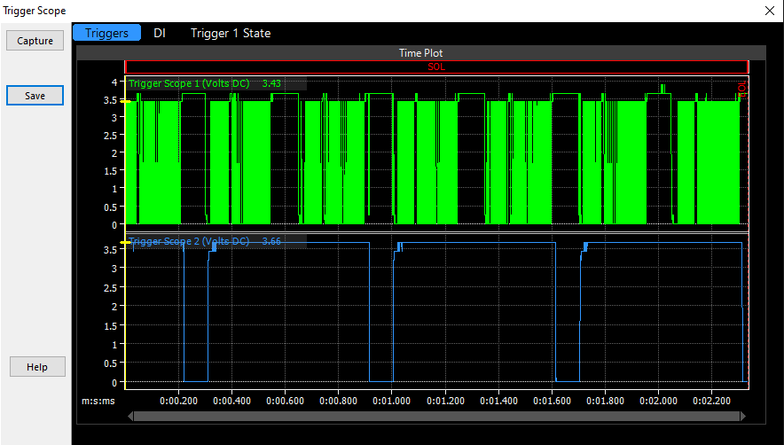
After re-assembly, I'm pretty sure the problem is fixed. I'm guessing the pull-up resistor is what drops the signal voltage down to 3.43V? Either way, It looks like I now have full 360deg resolution! I'll attach the scope log if you want to take a look. Camshaft sensor is not currently connected, as we were just trying to square away the crank signal.
As for the trigger scope log, I'm not sure if I'm doing something wrong? When I open the log in PCLink, it shows nothing. I also am not sure what typical log file size should be, and it's only 60kB.
-
4 hours ago, Adamw said:
Has it got an aftermarket trigger wheel on the front or is it still using the ring gear teeth?
Aftermarket on the front. Using a cherry hall sensor and a 60-2 tooth wheel.

-
Adam,
Engine is a 3.1L 4cyl in a Porsche 944 Turbo. Being new to link (coming from electromotive) I think I saved the scope and datalog to the link and not my computer. Battery is currently disconnected so I can’t pull them (or check to see if they are there). One thing I realized is that I’m not seeing about a quarter of the crank revolution so I’m verifying sensor and trigger wheel install.
-
This will be my first time running any type of camshaft position sensor, and I want to make sure everything is set up properly before I try and start the car.
I am running this crankshaft sensor (https://www.diyautotune.com/product/hall-effect-threaded-body-crankshaft-position-sensor/) running off switched 12v
-and-
This camshaft sensor (https://www.fcpeuro.com/products/audi-engine-camshaft-position-sensor-0232101027) running off 5v.
Having finally realized that they both needed pull-up resistors, I was finally able to get a successful trigger scope. What I'm curious about, is why the crank position sensor is only reading up to 3.43V, when I verified that it's getting 12v?
I am also worried that the mechanical timing between the two reluctors is too close.
Any input is greatly appreciated!
Thanks!
-
Perfect, thank you!
-
First timer here, so pardon if this is a stupid question.
I am prepping to crank my engine to prime the oil pump and verify trigger signals before the first start and noticed something that I wanted to verify wasn’t an issue.
I currently have the ECU set to perform a tach sweep (because why not?) and when I go into the software and turn the coils off, I noticed that it sweeps the tach after I make the selection. This also happens when I set them back to direct fire. My first thought was that it was some kind of visual indication that a command was accepted, but wanted to make sure I didn’t set anything improperly. I also want to just understand how everything is talking to everything else.
Thanks!
-
45 minutes ago, dx4picco said:
Most of the time the ECU will control a relay that feeds the fuel pump.
You will get +12V going to the relay and then the relay to a aux output that will provide a ground a the right time.
You can also control your pump with a pwm signal depending on the model
That's actually exactly what I was looking at as an option. I can supply the same earth signal that the original ECU did to the same pin in the existing car harness that I have to interface with anyways. It would reduce the amount of extra wiring I had to do, and also utilize existing fused relay circuits. I just didn't know if the link would look for a fuel pump, and not function properly if it didn't see something specifically assigned as that.
-
If the Link can be wired into the car to provide all the necessary connections to act like the original ECU, is there a requirement for the Link itself to directly control the fuel pump? Trying to figure out my options in creating the harness but couldn't find a definite answer in the manual.
Thanks!


Getting closer to first start, just want opinions on this trigger scope
in G4x
Posted
Adam,
I'm batting 1000 today...I meant the pull-up resistor in the software. I changed the wording in my above post so as not to confuse anyone who may read this thread. Before I turned that on, there was no signal on any scope I did. I'll search the manual for timeplot information and try to get it working.
Thanks for taking the time to explain this stuff!
After delving into the timeplot, I found where I can select individual parameters to show, and all works now. Thanks!