


theFiztec
-
Posts
16 -
Joined
-
Last visited
Content Type
Profiles
Forums
Events
Gallery
Blogs
Posts posted by theFiztec
-
-
Hi there,
i have a parralel install of a Link G4+ plugin evo 1-3 into my Daihatsu YRV engine. The stock ECU control idle, and AC while Link control fuel, ignition & VVT. Stock ECU need to remain as it is running Automatic Transmission.
I notice that when I pressed the throttle, the ECT reading fluctuate and if pressed throttle further ECT will reduce almost 10’C.
Does anyone had encountered this before? On the stock ecu TPS, ECT & IAT share the same sensor ground. However only ECT affected, IAT are ok.
-
On 4/14/2014 at 4:56 PM, Trent Treloar said:
Thanks Simon,
I've forgone the attempt to supplement the factory control and gone full control by the Link, It's all working fine now under the conditions I have set, however I now have a check engine light come up with a TCC lockup circuit error that will be fixed once I get my 5.6ohm resistor to simulate the solenoid.
One question though, is it possible to slowly ramp in the PWM up to a fixed figure? I was thinking ramping in over a one second period or less, making tcc lockup a fraction less harsh.
Hi trent, if you don't can you share how do you wire up your solenoid to Link and share your setup in link
-
1 minute ago, Adamw said:
The factory knock sensor is already connected on the Evo1-3, you do not need to do anything except turn it on and tune it.
Thanks adamw. i'll follow the evo 3 OEM pinout which knock input in on pin 58. since i'm using this ecu on daihatsu.
-
Hi @Adamw, Is this also apply to Evo 1-3 Plugin? Can your also share me the info. Tried wiring up knock thru ANVolt but did't work.
Thanks
-
I'm using the same idle valve together with 1zz throttle body on my daihatsu K3-VET. it runs with no issue.


My Wiring is ;
1) RSO (1) to Link AUX
2) B ( Battery 12V Switched/Ign)
3) RSC (3) GND
Here is my idle table DC

-
On 5/28/2019 at 10:27 PM, ericsiewkk said:
of a daihatsu yrv
Thanks! Will give it a try.
-
Hi all,
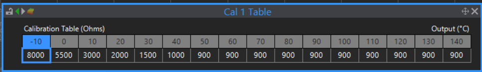
Im just wondering what are the Calibration table that i should use for the AC Evap temp sensor. Mine does have variable resistance in series with the evap temp sensor from the factory configuration to allow AC temp control.
i tried using bosch std calibration in the PC Link but i found out it was not too accurate as, my AC keep on engage and disengage too frequently even i set the controller at the highest temperature setting.
Just for info my car using Denso 077500-0710 thermistor for AC Evap Temp Sensor.
thanks
-
4 hours ago, Adamw said:
DI3 is also linked to the relay control circuit on Ign 4. So for instance if you put 12V into DI3 or turn on its pull-up resistor you will find ign 4 wont work.
Ok now i get it why IGN4 didn’t work when i wired up Neutral/Park switch to DI3. Already removed it and things is normal now. But will consider to run wasted spark. Thanks adam.
Is it possible for you to email me the schematic diagram for plug in Evo1-3 so that i can know how the hardware is connected and take into account in my wiring.
-
-
Hi there, Im using Link G4+ Plugin Evo 1-3. It has already tuned and engine has been running well for the past 2 weeks. However, this morning my battery died and i changed to new battery. After starting, engine run abnormal and after checking there is no output from Ignition 4. I run the test using the Ignition function. Please assist on what is the issue and if i can temporarily use Ign 5 to for Ign 4.
Thanks
-
For the moment the engine is running just fine without any trigger error. Will try to capture at higher RPM just to see what it will looks like. Thanks adam.
-
On 5/16/2019 at 5:43 AM, theFiztec said:
Here is a snapshot from the trigger scope.

@Adamw is it normal for the cam waveform to look like that. The first tooth amplitude is shorter than no 2 & 3
-
A quick update. I have managed to installed and start the engine using 2NZ VVTi trigger setup..Here is a snapshot from the trigger scope.
On 5/3/2019 at 5:11 PM, ericsiewkk said:u need to cut N1- to the stock ecu.
This one really helped me out to get the auto transmission to shift properly as i did a piggyback style installation.
-
Yes adam i did click the Capture button. For the sensor i believe the connection is correct right?
For trigger i will try to use the Subaru EJ20 quad AVCS trigger mode.
43 minutes ago, Adamw said:There is no user configurable RS232 in our ECU's (or any other ecu that I know of), only a couple of preconfigured streams designed to be used for older motorsport dash displays.
Noted on this. Thanks adam.
2 minutes ago, theFiztec said:For trigger i will try to use the Subaru EJ20 quad AVCS trigger mode.
Just to double confirm on trigger setup. Below is my trigger wheel pattern.

I believe it is 36 with 2 missing tooth. Isn't it the same with Toyota 2NZ?
-
Hi there,
i'm having trouble to get my engine start up. When i look into trigger scope, i think it is not as what it should be. Here is the screenshot of the trigger.

My engine details and ecu type :
Daithatsu K3-VET
Trigger pattern 36-2 on crank
3 on camshaft
Using Link G4+ Evo 3 Plug in.
Trigger 1 is connected to crankshaft sensor, while trigger 2 is connected to cam sensor. Both are Variable Reluctance type sensor. Below is the diagram of my original ECU.

I did my wiring as such that i connected N1+ (Crank Sensor) to pin 69 (Trig 1) on Link, N2+ (Cam Sensor) to pin 68 (Trig 2) on Link and both N1- and N2- to sensor ground on pin 72 on Link.
Need help on this. Is there any mistake i make on wiring or there is any other problem. I use Toyota 2NZ-FE in trigger setup.
My second question is, can i use RS232 on Link ECU to send data to my Transmission Control Unit since my ECU did use serial comm to comm betweem ECU and TCU using GND, RX & TX.

Thanks!


ECT Drops Under 50-100% TPS
in G4+
Posted
Ok thanks for the reply. I will figure it out myself. Thanks.