


SC350Z
-
Posts
16 -
Joined
-
Last visited
Content Type
Profiles
Forums
Events
Gallery
Blogs
Posts posted by SC350Z
-
-
5 hours ago, Adamw said:
What ecu do you have?
Probably easiest to connect it to your existing bus for the lambdas since the wires are already there. Set up instructions are in the power tune manual.
Hi Adam, it's a G4X for Nissan 350z ....
Powertune dash has 2 wires to connect to CAN port on ecu. Was wondering what port to use on ecu. Or as you said if I've to connect to lambda bus directly...In this case, how does it work?
Thanks
")
-
Dears,
I have to wire the Powertune dash to my G4x. (where there are already 2 link can lambda connected onto the G4x).
Where shall I connect the cabling (Can H/L) from the powertune dash to what port on G4x board?
What cable / extension do I have to buy for G4x?
And finally...what setting are needed on G4x?
Thanks for you help
-
17 minutes ago, Adamw said:
Go to your E-throttle target table and adjust the relationship between pedal and throttle to suit however you like it. At the moment it is set up to give easy movement below 3000RPM and more aggressive feel at higher RPM.
Dont adjust the top row, but do whatever you like with the rest of it.

Hi Adam, thanks for your reply.
I will try to increase the lower rpm e-throttle target... and see if it improve the pedal feeling.
Concerning e-throttle PID, are they ok like this or any fine tuning is needed to better correlate APV and TPS position?
-
Hi,
was trying to figure out the correlation between APS and TPS readings. Seems from the log attached that they are not following each other, they are always misaligned.
The APS readings are lower compared to TPS and at some point (higher rpms) they are the other way around (APS higher than TPS). Is it related to my PID settings or what?
Throttle response in general is sluggish most of the times and when pressing the accelerator, it's not a crisp response at the pedal.
Attached the log and map. Can you help?
thanks.
-
On 3/31/2018 at 9:51 AM, Adamw said:
The VQ35 comes in both two variable cam & 4 variable cam versions.
Connect the crank to trigger 1.
RH Inlet cam to trigger 2.
LH Inlet cam to DI1.
VVT solenoids to any Aux 1-4.
The crank and cam sensors on this engine are powered by 12V.
Hi Adam,
I'm reviving this thread for a question concerning my trigger scope, on a Link g4+ PNP on VQ35DE engine.
The filters for trig1-2 are set to "low". Cam angle test led to 44.5° for RH and 161.5° for LH cams. (quite different form stock settings)
This is the scope I got, while warmed up and idling. Is this fine? Or anything wrong with it? Can you please check? Thanks.

-
On 10/14/2019 at 10:03 AM, Adamw said:
They shouldnt change much at all, apart from a bit of slop in the timing chain. How much change are you seeing?
Trigger offset will vary on every engine, this is due to stacked manufacturing tolerances on all the mechanical components, things like crank shaft keyway, pin indexing, pulley marks, front cover pointer, trigger wheel indexing, etc.
The referenece timing can be any number you like, this is just the value that you want to aim for when you are checking the timing with a timing light.
Hi @Adamw , sorry for being late.
The difference i see during cam angle test is the following:
Inlet RH ==> below lockout (1000rpm) is 43.7; above lockout (2000/2200rpm) is 45.6
Inlet LH ==> below lockout (1000rpm) is 160.5; above lockout (2000/2200rpm) is 161.4
I did some logs with the inlets settings above, attached. What do you think?
I see the slope of the inlets always shifted and not following correctly the target....regardless (it seems) from the value I input....but anyhow if I increase the inlets degrees values, it get closer to the higher VVT target (38°), otherwise the inlets stay always 1/1.5 degree below..... is there anything wrong or what? any idea?

-
11 hours ago, Adamw said:
Yes, you should enter the correct offsets (both on DI and trig 2) for the VVT position to track correctly.
It will not affect the trigger or ignition timing, all you are doing is telling the ECU where the reference tooth on the cam is in relation to TDC on the crank.
Hi @Adamw , thank you very much as usual really appreciate it.
Just a clarification about the readings of the cam angle test. I've revved the engine above the lockout and then left the foot off the pedal, so the revs fell below the lockout providing those values. is that fine? or should I keep the revs above rpm lockout and get those readings? Which are higher by the way....
Another thing, the trigger calibration I have is different form the default settings for VQ35, hereafter:
Default is -2 and 10, current mine is -1 and 15. Is this fine? Why is it different like this?

-
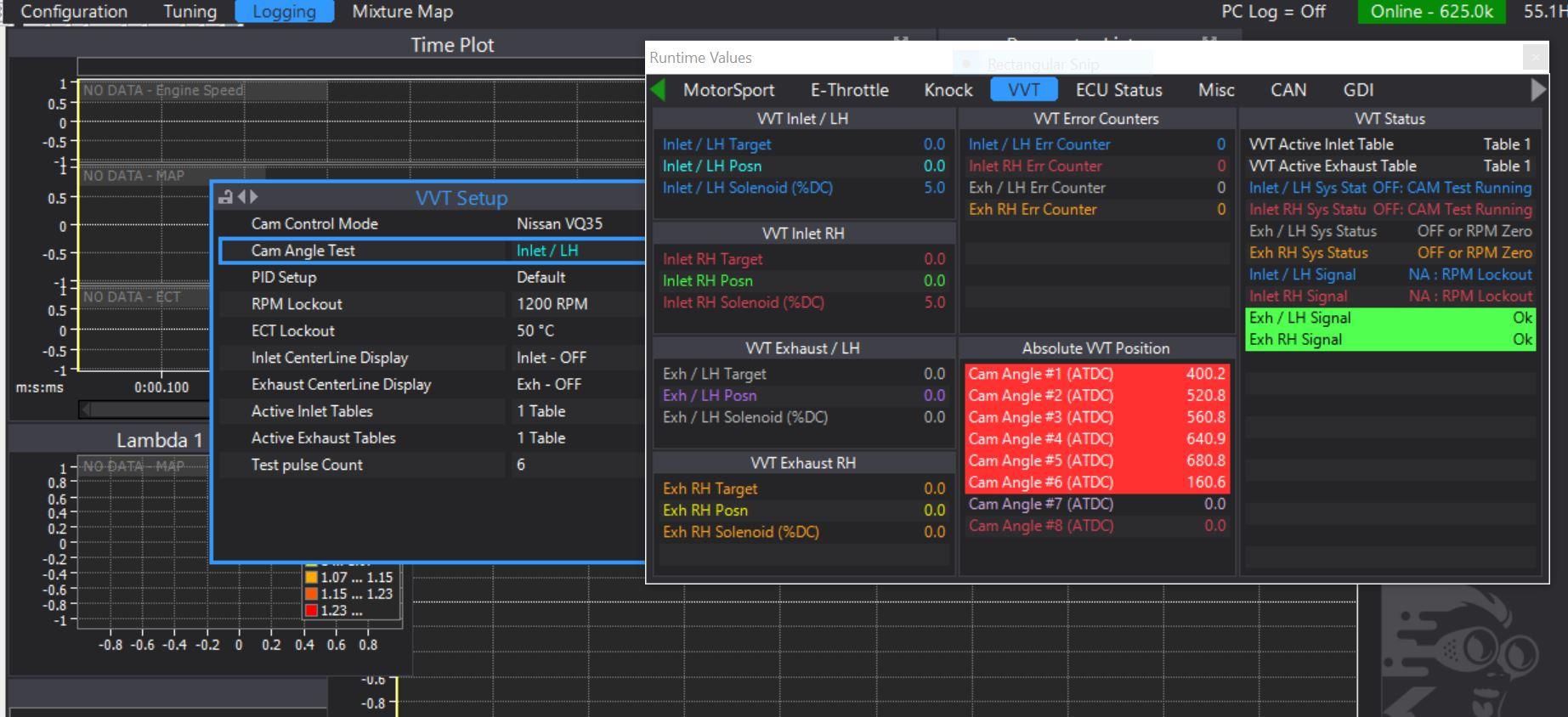
I've run the "Cam Angle Test"......
in the table DI 1 - VVT Cam position, the Offset value is set to the default VQ35 value, 158.5° ATDC.

the value reading from the test (lowest) is 160.6°.

Did it also forTrigger 2 VVT referring to RH inlet... which is set to 42.6° but from cam angle test the value should be 43.6°.


Question is, should I change-update both the Offsets values of Trigger 2 VVT and VVT Digital input?? Or just the Trigger 2 VVT?
Is any other change needed on other triggers a/o Ignition timing?
Thanks for your help guys...
-
Hi @Adamw, one question about VVT inlet target. I did some pulls and logged the results. I found that the Inlet LH / RH cams positions are aligned between them BUT are NOT aligned with the VVT inlet target ..... I don't have cam positon errors whatsoever...
If i do a time plot of LH/RH positioning compared to the target...it looks like the curves of LH/RH positions vs target are shifted and even when overlapped the target is not matched...is that even possible?
Please let me know your thoughts. Thanks.
-
On 8/26/2019 at 7:06 PM, Rossobianconero said:
the dyno is gonna be your best friend for vvt tuning, cause is not na you can just see your lambda to check that your VE is increasing or decreasing (more or less power). cause you are FI sometimes you can see higher boost but doesnt necessarily mean you are making more power (at least in turbo engines)
Yeah clear. In case I will try to increase the intake cam advance like 4 -6 degree (where it is 0 @ 60-80MAP), is there any issue with valve to piston clearance?

-
12 hours ago, Adamw said:
It would be very unlikely to get real knock at redline. Typically the knock RPM lockout would be set a little lower than the RPM limit so it doesnt matter if the limiter causes some false knock.
Yes that is fine.
Hi Adamw, thanks for you reply!
here the knock table set-up. The rpm high lockout is set to 7000rpm, but my rpm table limit is 6700rpm. Shall I decrease the lockout to 6600rpm?

This is the knock threshold setting by the way:

May I ask your opinion on these settings of VVT and Ign.Timing? How do they look like? I run a supercharger which push 0,86bar max @6700rpm (no catalityc converters) with 264/264 cams.


About "spark duration" in Igniton Main Table, it is set to 1.5ms (by default) with "direct spark" mode. Since the default Dwell is 3ms but I run it around 3.6ms, shall i increase accordingly also the "spark duration" to for example 1.7ms? Or it doesn't really matter anyway being a "direct spark" system?
-
On 8/8/2019 at 11:12 PM, Rossobianconero said:
i dont see any tune.
Hi! Modified the RPM Limit table with Advanced Mode "ON", hereafter. RPM limit is 6700rpm.

About "Limit ignition Trim", shall I put a negative trim for timing?
Sometimes the ecu records a kind of "ping" of knock (on log there is spike quite close to the threshold) when reaching RPM limit.
On 8/8/2019 at 11:12 PM, Rossobianconero said:thats right, you can even lower the dwell until you lose power on the dyno or have misfire (sometimes you are gonna see lost on power before hearing a misfire), and then rise the dwell until you stop gaining power, you want to have as lower dwell time as you can.
This is the current setting:

It works between 3.5ms to 4ms, but it never reach the upper limit. it stays around 3.6ms, then it goes down with rpm. Seems to be performing well like this. tried to increase it but was not gaining anything...also the sound at exhaust was not that good... it's better with the current setting. Dunno if it makes any sense ...
About MAP/BAP.... My ecu is already tuned, therefore I did not run any further MAP calibration.
The BAP reads around 97.6Kpa with ignition on and engine off. MAP reads 98Kpa (1.14V on AN9 analog input)

.....they are quite aligned, is that ok?
Thanks!
-
On 7/9/2019 at 11:22 AM, Adamw said:
I would only increase dwell if you were getting noticable misfires. If it ran fine with the orignal lower dwell then you are only heating the coils more and shortening their life by giving it more dwell.
Hi Adam thanks for reply and your advice.
No i don't have any misfire so far. at least nothing logged into the ecu. Only event I have is "rpm limit"....which was not happening before, or at least I didn't notice since ecu statistics was reporting a max engine speed above rpm limit of 6700rpm. Now seems to be cutting around 6400/6500rpm from logs. Anything I can do?
Attached my tune, would you be so kind to have a look? just for an advice in case of any.
-
Anyone?
Here the dwell setting I'm using with Okada coils.

Attached the log I did. Only variation was the dwell (before was 3ms, as per stock 350z map dwell).
All parameters are logged. Can someone check it and let me know?
-
On 10/16/2018 at 6:42 AM, Adamw said:
Our 350Z base map has injector deadtimes and ignition dwell times for the stock injectors and coils.
Hi Adam, sorry to up an old 3D. I have the N350+ on my 350Z. My car is supercharged (built engine) running @0.83bar and I've already the tune done.
I've seen the dwell time tune setting is between 3.9ms and 3.5ms @13/14v. Coils are stock ones.
Now I have a set of Okada plasma direct to install. Do you know if any modification on dwell time is to be done? Maybe increasing a little bit around 4ms flat @13/14v?


Powertune dash wiring and cables / ports on G4x
in G4x
Posted
@Adamw and @Timboj
Great guys, appreciate it") I will have a look and update this thread once done.
I will have a look and update this thread once done.
Thanks a lot.