

.jpg.398baa0f2b9b9e93a38655ae0b22dc46.jpg)
2.0L_turbo
-
Posts
91 -
Joined
-
Last visited
-
Days Won
1
Content Type
Profiles
Forums
Events
Gallery
Blogs
Posts posted by 2.0L_turbo
-
-
hey everyone, like the title states I am looking to start tuning this weekend and am hoping to get some general tips.
1- One thing I am curious about is the Quick tune function, I am aware it does not change ignition timing and only changes the fuel table. I have set up all of the settings in the options menu for it however I am curious about is Load center tolerance, does a lower percentage make the cell easier to be targeted?
2- should idle tuning be done before or after the driving tune?
3- Something I noticed playing around a few weekends ago is when I was trying to get my idle tune done is I would manually change a cell where I was hovering in, after changing the cell and getting it around 14.7 afr the car would either idle up or down and change where in the map it is so I would then adjust that cell and this became a repeating cycle until 1 or more cells are at 0. Just trying to understand what I was doing wrong here.
4- should I be trying to tune the idle with or without the isc turned on to start with? I ask because a buddy of mine with a similar setup said it made it way easier to do it with it turned off then once that was done turn it back on and fine tune it from there.
I am open to any other suggestion and help, I will also upload a file of what I have after I am done messing with it on Saturday but hoping to learn a bit more before I go into it then.
thanks for any and all help on this!
-
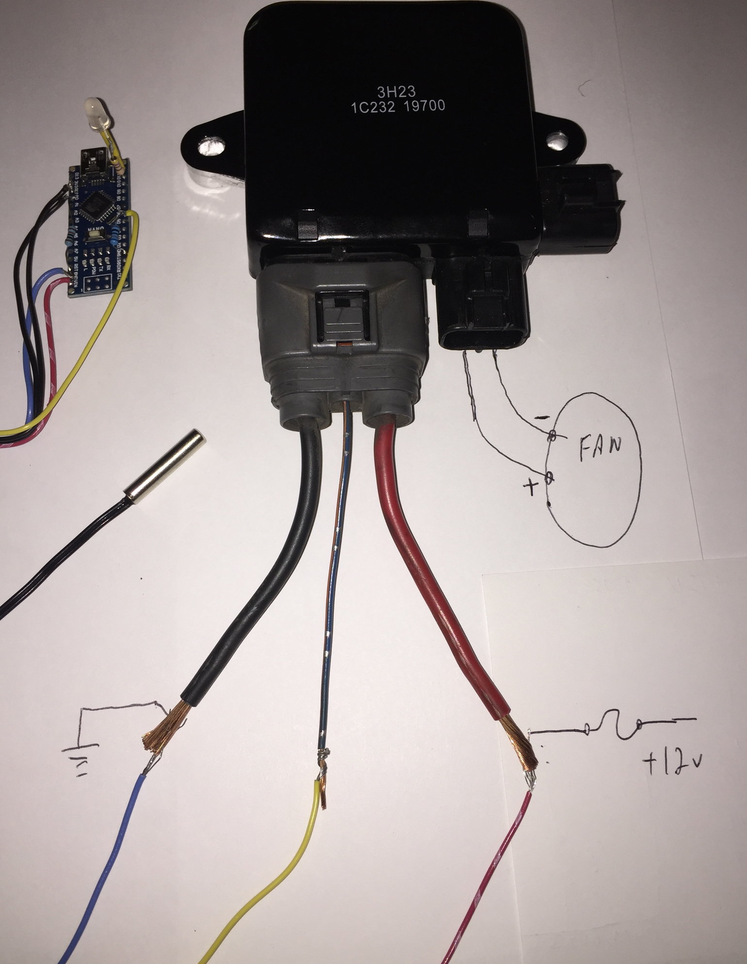
hey guys looking to set up a fan control module in my car soon and just want to make sure I understand how to get this all wired up properly. I found this pic on google which makes sense and then when it comes to setting up the controller does this sound right,
when fans are off duty cycle is 100
when fans are fully on it is 0
the middle wire on the 3 pin plug gets wired to a spare aux set as a GP PWM signal and the frequency should be 3.9khz
If I am missing anything please let me know, thanks!
-
Solved it!
I figured out my problem, so with the way our relay was wired it would pull pins 63 and 66 to ground which is right, but what we missed is that once the engine is spinning on the stock ecu it also pulls pin 56 to ground as well and this keeps the fuel pump running. How I tested this was I temporary grounded out pin 7 on the MPI relay which leads to pin 56 on the stock ecu and then fired the car up with the link and she kept running for the first time. So I think all I need to do now is add pin 56 to 63 and 66 and we will be set.i will also add this to the adapter harness thread incase others try and copy it. I can able to now set the master fuel to 20. I now am facing a weird wideband issue but will do some testing on then and post if needed.
Edit* ok I realized a safety issue with wiring it how I described above, the proper way to do this would to be using another spare input and using it for fuel pump relay control and setting that to pull low after the car is running this makes it so that the fuel is not pumping as soon as you turn the key to the on position and continue to pump after the initial prime of the system. So what I will be doing is using another one of my outputs for coils likely B11 or 12 and setting it as followed
pump control method standard
fuel pump relay output ign 6 or 7
aux ign test off
aux ign active state low
prime time 3 seconds
hope this helps!
-
while out testing the car today I noticed the relay is shutting off and right after the car goes lean so I believe that is the issue here but how can I fix that?
-
1 hour ago, Adamw said:
Can you give us a log of it running longer with the throttle open or whatever. Do you have ECU hold power wired so that the stepper motor is resetting at key off?
I can get you a log in about 5 hours time I'm just at work at the moment, and I have my relay wired in like this to activate the MPI relay as per your request from my harness adapter thread.

-
the fuel pump is controlled by the MPI relay, here is a link to another forum explaining what all the mpi does and how it operates, but I can keep the car running if I give it throttle it just wont stay running on its own right after the initial start up.
https://www.dsmtuners.com/threads/1g-basic-ecu-mpi-circuit-function.435961/
58 minutes ago, Adamw said:Could the fuel pump be stopping? Is there fuel pressure?
not sure, the car is currently still on a factory fuel pressure regulator so I currently have no way of monitoring fuel pressure but it would seem odd cause as stated I can keep it running if I apply some throttle for a few seconds. Is there a way to increase or decrease the time it takes for the ecu to pick up the cam angle sensors signal? maybe what is happening is it has not got synced with the sensor yet and needs more time to find it? I had a similar issue like this while using an old aem ecu where it wouldnt sync to the cam sensor fast enough and was a known issue with the old v1 aem on these cars.
Edit* Just noticed in my tune file the IAT fuel correction was enabled, when I did these tests the car was already warmed up from me driving home using the modded factory ecu, so with the iat temps being over 180F its pulling 3 points of fuel out if im reading that chart right, would that be enough to cause the issue and should I disable that until the idle tune is finished and working properly?

-
just curious if anyone has had a chance to take a look at these logs, really hoping to get to do some tuning with the car next weekend
-
here are some data logs i had it idling for a min or two but the idle was really high around 2500rpm, tried cycling the ignition and then it went back to dying on start up. what the fuel number is referring to is the master fuel ms
talon fuel 15.llgx talon fuel 18 no isc.llgx talon fuel 18.llgx talon fuel 20.llgx talon fuel 22.llgx talon fuel 25.llgx
-
2 hours ago, Adamw said:
Your master fuel will need to be much higher for 550cc injectors, I would try it up around 20-25ms.
The only error you have in the map above is for AN Volt 3 (TPS) being above the error high. But that shouldnt happen if the wiring is ok and TPS is working correctly. If you clear the codes, what causes it to come back?
I'm about to take a log is there anything specific your looking for that I should add?
-
injectors are 550cc low impedance running resistor ballasts, I can try and take one later tonight when I get off work. for the errors I am getting is it safe to set high and low voltages to 0 and 5V?
-
Here is the file from when the car starts runs for 2-3 seconds then dies, any help on this would be greatly appreciated.
-
Ok so an update, I remade my map/iat harness and added in TPS and ran them directly to the ecu and ran all the tests again. Thankfully this time it worked!

So now I was able to calibrate my map and TPS for the first time successfully and saved it to the ecu. Tried firing up the car and it started but dies seconds later. I will add a file of the tune in a hour or so and hopefully see if there is anything I'm missing.
-
Okay thanks so then that rules this out
-
I'm curious do all the sensor grounds on the link ecu need to be connected to something? I'm having an issue in a different post I made but I'm curious if what is happening is that one of the sensors grounds is specifically for say the analog inputs? If so this may explain why my map and TPS are not working and all I need to do is connect the sensor ground up that I left out. Also there are sensor grounds that I have hooked up I just didnt use them all.
-
8 hours ago, Adamw said:
This should show 5V with the 5V pin bridged to the signal pin. Since it is only showing 1.21V suggests you have a wiring issue. Do you measure 5V at the TPS plug?

Yea I measured that and was seeing 1.7 ish volts. Thinking I may bypass the factory harness for map and TPS and make a sub loom
-
this is a diagram for how to hook up the ebc and yes for your needs a 3 port is more then enough. Myself personally if the boost pressure is only as low as 15psi I would be just fining a spring combo that hits your desired pressure but that's my personal preference.
here is a diagram showing how to hook up a 3 port EBC.

-
That would depend on a few things, would you like the ecu to control the boost pressure? If so you will need to get a electronic boost controller solenoid. as for the vac lines this all depends on the wastegate and how many ports it is. Every set up is a bit different so with out knowing exactly what you have its hard to help.
-
8 hours ago, Adamw said:
You could unplug the sensor, watch the analog input voltage in PC Link, it should show 0.00-0.02V when unplugged, then bridge the 5V pin to the signal pin in the TPS loom/plug, the AN Volt should then show 4.98-5.00V. If it doesnt that would suggest there is a wiring issue somewhere.
ok so I tried to do this but I am not sure if the value I am seeing is what you are looking for to go to 5V. I believe I seen a post you had commented on showing a picture of a tab in link that displayed analog input voltages but I do not see that on mine. here are some screenshots of what I got when I bridged the two as well as what is is when the connector is plugged in.
connector plugged in

connector unplugged

connector bridged

hope that helps
-
Ok so update,
Just tested sensor ground as you asked, I did it with stock ecu and the link set up. On all tests at the maf plug, my loom, and TPS all are the exact same at 0.02- 0.03 ohms. My next question should the signal wire for the map be outputting more voltage then the 5v+ wire? With the ignition in the on position I am getting 2.2mv on the 5v+ and 7.2mv on the signal wire for the map sensor. And TPS is seeing 1.7v


-
12 minutes ago, Adamw said:
With ign off if you measure between the sensor ground pin and battery negative with an ohm meter you should see near 0ohm.
is there any other tests I can do along with this one to figure out why the TPS is not working?
-
Hey guys,
I made a plug and play adapter for my link storm X to connect straight into my 91 Eagle Talons harness. For the most part it works awesome but I am having an issue where my TPS and my map sensor are not working. At first I thought the map sensor wasn't working because I had made a adapter harness for that to plug into the factory mas air flow sensor connector on the engine harness side, so I checked to see if the harness had continuity and power being delivered on all appropriate pins, which it did. But then I noticed that my TPS was also not functioning and with both being AN volt and using a sensor ground I got suspicious that maybe the issue is actually the sensor ground not working as it should. I know my TPS is functional as it works just fine on the stock ecu however the map sensor never came on this car so I was tapping into the sensor ground for the MAF sensor but I also used that sensor ground for the IAT sensor and that is working just fine. And yes I did calibrate the TPS and it sits at 0.01 and MAP shows 0.00
So with all that said how can I go about testing the sensor grounds to see if maybe they are my issue. If needed I can attach a tune file but the car has not started yet so there is no real log just the evo base map.
-
Perfect thank you.
-
6 hours ago, Adamw said:
What I often do is input the values you have, then change the deadtime table to graphic view (K key) then adjust the in between values using arrow keys until you have a visually nice curve through the known points.
is this kinda what you were taking about?

-
Awesome thank you Adam I appreciate the help, just got the last piece to my puzzle today being the iat sensor, it gets the bung welded in tomorrow then it's time to get tuning!


lambda not reading on software but shows voltage?
in G4x
Posted
having an interesting issue at the moment went out to try and start tuning the car tonight and got everything set up and now on the software the lambda does not show anything. I am sure it is something simple and stupid easy fix but I have no idea what it could be. To make this better this worked fine the other night with no changes besides adding a fuel pressure regulator but in no way did that change anything to do with the wideband.
in the software an volt 6 reads voltage from the wideband but does not display any reading. another odd thing is all the other an volts are reading slight voltage like .01 - .03 yet those are not being used for anything and do not even have wires connected to them.
here is the tune file as well as a very short 7 second log as nothing really changes but figured it may help to see?
I also have the tune file but it is 439 kb and I cannot upload it due to size limit of 418kb
any help on this would be awesome cause I really wanna get tuning this thing already.
ECU Log 2022-05-21 11;51;09 pm.llgx