


mjb214
-
Posts
86 -
Joined
-
Last visited
Content Type
Profiles
Forums
Events
Gallery
Blogs
Posts posted by mjb214
-
-
I was able to get up and work on it some more today. The spark seems to be changing after 1 or 2 sparks could it be set to the wrong number of teeth on the Crank AS? I took a scope and it looks like the Cam trigger is not working correctly, I had issues in the past with the wiring directions I paid for having a lot of stuff backwards, could it be because the + and - are swapped on either trigger? Could it be ground noise? ( I plan to follow the ground line back and verify it doesn't have anything T'ed into it that shouldn't be.
It also seems to stop sparking after 4 or 5 revolutions, could this be the computer realizing the spark is erratic and shutting it off due to being way out of timing? When I set the timing per the first fire the it keeps moving each time. In case the trigger scope didn't save right I took a jpg of what it looked like.


2gr turbo mr2 base.pclr Trigger Scope Log 2019-03-2 1_35_20 pm.llg Trigger Scope Log 2019-03-2 12_29_44 pm.llg Trigger Scope Log 2019-03-2 12_30_36 pm.llg Trigger Scope Logpm.llg
-
Thanks for the clarification, makes sense
-
CJ,
I calibrated it a few times, I'll go back and do it again on Monday. I am running 93 Octane and most likely will stay with 93. I'll look into changing the crank enrichment and see if it helps.
For the ISC I am just trying to get this started and idling to get it to the tuner who will actually know what he is doing. Is there some basic things I can set up in there myself? I pulled it up and it looks like Open Loop - E throttle is what I would want to work with. I can ignore fan, power steering and park for now I assume since they won't be relevant as I am not letting it warm up yet, the power steering is electric, and it's a manual. The A'C is not hooked up yet so also not a concern for now.
The tables seem like where I should start but what are some reasonable values. The temp has been variable here 32F to 55F (0C to 13C) but it is slowly warming up here. (Virginia, USA)
I will certainly run the Trigger scope on Monday and re calibrate the throttle.
The timing mark I checked with the light so it should be at 10 BTDC and that is how I set it in the software or so I think. It is hard to see as this motor wasn't intended to be in an MR2 but should be within a few degrees and shouldn't stop it from starting. I'll be fine tuning everything with the tuner.
-
I will be back to the shop Monday and will run the trigger scope. It's about an hour drive, wish it was closer so I could step outside and run it quick for you.
I tried several around the 150 range with no luck. We put a jumper spark plug wire on the number 1 cylinder for the timing light. It appeared to be right at 10BTDC when I stopped but the mark wasn't shown every flash and I didn't want to just keep cranking on it. We did 2-3 seconds each try and then change the timing and tried again. We tried maybe 15-20 times at various angles.
I don't have my pullup resisters wired in yet if that might cause errors, I didn't see any errors coming up on the screen.
-
I didn't want to start another thread so I am going to continue the work here.
I ended up fabricating the whole exhaust before trying to start it again and working out a lot of other small details.
I tried starting it again today and just couldn't get it going. I believe I got the Crank Angle to be at the correct 10BTDC with the timing light, it took 205 in the calibration adjustment to get there. I feel like either the injectors or the ignition is not correct. I took a log and have the map attached. Is there something obvious?
Thanks for the help, let me know if you have questions. I'll be digging through the help files as well.
-Mike
2gr-fe turbo base 2-27-19.pclr Log 2019-02-27 1_34_43 pm.llg
-
Yes I think it's a 23 degree angle tilt of the motor which is awkward. Also the number 1 cylinder is under the intake manifold. I stuck the gun way down by the pulley and just kept changing the adjustment until it showed up.
I had a fuel leak and a back fire which lit on fire. Fire extinguisher was handy but will have to pull all the wires off and recheck to see if anything is damaged. Not to mentioned the fire extinguisher dust everywhere.
I believe we got it to 10 BTDC by using 190 degrees as the adjustment. It still seemed off but the light showed it correct so once I sort out any damage my friend is going to stop by and see if we can figure out why it still isn't firing up.
-
Great thanks. I'll change it back to falling and try changing the offset a few times. Glad I don't have to manually check the Crank angle, it's a pain to get the AC compressor off.
-
I rechecked most things. I put a camera wire down to check the Crank sensor but the wires are wrapped so I couldn't check. The coils all work now, but the timing is off. I didn't have a good way I could think of to hook up my timing light as I have only used it with spark plug wires. Do you pull out the # one and put a jumper wire in between the coil and the spark plug?
Here is the log (let me know if the log works this time). I noted that the Trigger2 for the 1 Cam Sensor was set to Falling and the help file says rising. So I changed that but it still was firing way off. It could even be 180 off, next time up i'll pull off the AC compressor so I can get to the Crank Angle sensor and check to see if the wires are correct there.
Any other ideas I should look for?
-
Yea, I'll be rechecking everything now. It's a good learning experience I guess even though it's wasted about 3 months since I can only work on the car every so often.
You guys have certainly saved the day so thanks a ton.
-
You're Right. I pulled my stock 2GR harness out and it's backwards. That is incredibly annoying since I didn't do the connectors I paid a bunch of money to have the connectors and the wiring diagram made since this was my first time wiring a standalone. And now I will have to check every connector.
Thanks for helping me figure this out so far the two major issues were the TB wired backwards and the Coils wired backwards both of which I paid someone else to do. I'll go through and compare all the other connectors to the stock harness for correctness and hope there are no other issues.


-
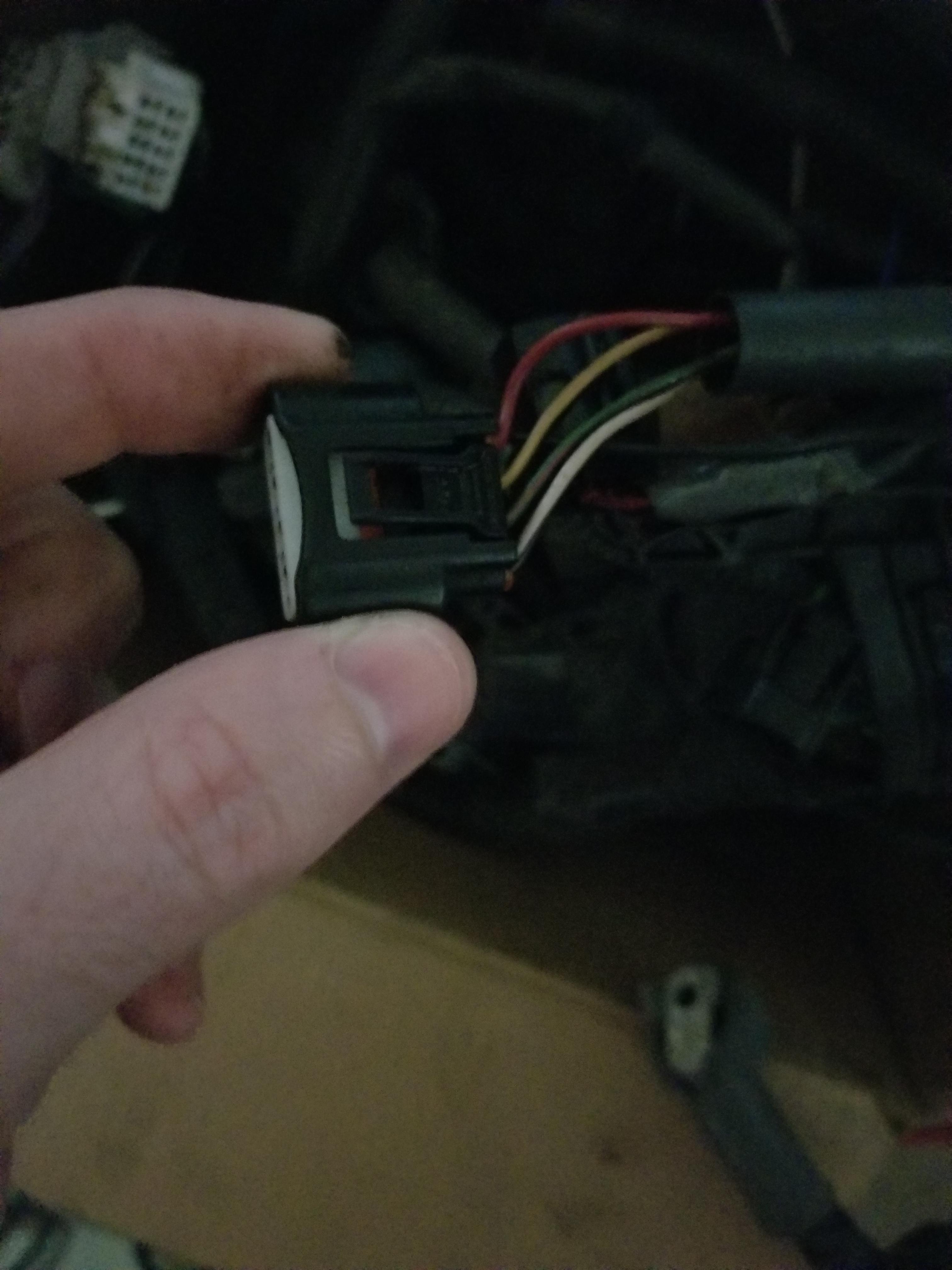
I have the red wire (pin 1) in the right most part of that connector when looking at it as shown in the photo. attached is the wiring diagrams from the 2016 Toyota Avalon (donor car) B36 is coil 1 for reference. As I understand this matches how I have it wired, hope I didn't misinterpret it !


-
They have power to pin 1, ground to pin 4, and trigger to pin 3. Pin 2 is empty but I believe that is just a error pin for the stock ecu. I checked and the power and ground are both working, I did run the grounds all 6 coils to one ground on the chassis. The coils are the stock 2GR-FE coils.

-
I was finally able to get back to the car. I have not been able to get the coil's to fire. They have full voltage and ground but when I put them to test I don't hear it firing. Also the coils were heating up quite a bit, I would guess like 110F degrees to the touch which seems too high to me. Is it pulling too much power? I was trying to do some research but couldn't figure it out.
I attempted to take a log while the car was cranking. Hope I did it correctly
-
That is awesome you rock! I had changed the Speed sensor before I must have been an idiot and not saved it, glad you caught that. I should be up next weekend to upload this and start finalizing my radiator lines. I am practicing my TIG welding the next two weeks so I can start exhaust fab and get the turbo actually installed. Once I do that I'll likely run no I/C and 5 psi for my first tune. Then decide if I go Water/Air or Air/Air and weld up the intake piping to match which way I decide. I am leaning towards water/air so I don't need to add a tank and pump and lines all the way to the front.
-
So you were right. The Toyota runs it backwards. It calibrated and appears to be working perfectly!!
Here is my latest map. Any advice for preparing to crank it? I still have to put in the correct injector information (attached) and correct the sensors as they appear off. I finished my fuel lines as well.
I still have to make my exhaust and intake so the turbo just has the oil lines hooked up and is hanging in place for now. I was thinking about trying to start it straight headers no turbo first just to verify everything works. It would be nice to be able to start it to get it onto the trailer for when I take it to the tuner.

-
This weekend I'll double check the wires. It's possible they are swapped but I was pretty sure I checked everything twice before hooking up the battery. The diagram I have shows Pin 1 of the TB connector to be V- and Pin 2 to be V+ for the motor. This appears to be correct from the manual I bought. So I will verify I didn't swap them.
Good to know about the error being about not being calibrated, thanks.
-
I was able to get a new battery and I think that was part of the problem. From what I can tell when the key is on Accessory power is to the relay but the relay isn't switching on and says there is a error on Aux 9/10 for power input. I took a video hoping to give a better description of what I am seeing in case I missed something. I did verify it has sufficient volts even when the TB is activated. The battery is brand new and had a charger on it during the whole process.
https://drive.google.com/open?id=1DRx1rvGfosTN0tBkcKLK4ZM5nA5ulATZ
Another question if I am not using all of the sensor grounds on the ECU do they have to be grounded? I had originally had all of them grounded but I disconnected one of them wondering if it was getting back signal. I also moved some power grounds to their own spot on the engine to better isolate grounds.
Thanks for the help.
-
Yea I did the same. I had 12.5 when I checked but I don't think I checked while it was trying to calibrate. I am 95% sure I got it wired with the correct + as I had the throttle open all the way before I added the relay. I believe it moved from about 5% to about 10% maybe not even 10 then failed. It happened in about 2-5 seconds from starting the config so I didn't have a lot of time to investigate and it was just me working on the car. This weekend we have the hurricane coming (which canceled my lemons race) so I won't be working. Next weekend I"ll be back up at the car to run any tests you think will help.
-
The throttle plate moved but only a few degrees. When I hit F12 it looked like it had full power to it. Prior to wiring in the rely the throttle plate would move fully but would fail calibration due to not having the relay. So I feel like it should have power.
I did cheat and pull power off the relay block after the fuse rather than run a new wire since the battery is in the front and the engine is in the back. But that should be the same since that is the power coming to the relay box as I understand.
How can I verify it is getting enough power?
-
2GR-FE Test 9-9-18.pclrthrottle error 9-9-18.llgI wired in the relay and set it up and it appeared to work but got a 80% error and wouldn't finish calibration. I tried changing the inputs after reading some other posts but couldn't get it to run the calibration.
The AP calibration seemed to work just fine. I believe I captured the log of it happening and also attached the latest map. I still haven't touched any of the fuel mapping or sensors yet to calibrate them. Just trying to get the e-throttle to work.
-
awesome, this weekend I'll get that setup and then try calibration again and take a log of it.
-
I unpinned and put the inj and coils in the correct order. The cams were already correct.
I rewired the power to include the relay but I don't have a Aux port open for the last wire to control it.
My aux ports are as follows
Aux 1-4 are VVTi
Aux 5 - Fuel Pump Relay
Aux 6 - Waste Gate controller
Aux 7 - Tach
Aux 8 - Engine Warning light
Aux 9/10 DBW /APP
I am not sure if I can retain function of the CEL if I don't use one Aux for that, but obviously the throttle body is more important than a dummy light so I am ok cutting it out if I need to. Wasn't sure if there was another way.
-
Well I'll run back through everything and verify it. I'll be at the car tomorrow for a few hours. I might be misremembering how I ran them, I'll be checking each wire when I get there since my instructions I followed appear to have some mistakes.
-
Ahh, gotcha. Excellent. So I ran all my main power off of that pin already, just didn't realize it was also labeled as Aux9/10 power.
Will a standard normally open 12v 30amp relay work?
So should I wire the relay in for all going off of this power. It would make sense since then it could shut off power to everything rather than just the throttle body. Is there anything in the below list that should retain power and bypass the relay?
VVTi power 1,2,3, and 4
Alternator pin 2
EB1 pin 2 (This goes through the main relay with a 15 amp fuse)
Diagnostic pin 12 (this is for the 92 MR2 old school diag connector)
O2 sensor pin 4
ECU-B pin 1 (body harness)
ECU-B pin 2 (body harness)
Wastegate pin 1 (power for boost solenoid)
I have both B pin 5 and A pin 5 together, since that is how the wiring diagram I got showed it but perhaps it makes sense to keep them separate as it would allow you to turn off only certain things. Currently if I splice that wire and put a relay in it will shut off the main relay power as well. But perhaps that is the point here.. Let me know what you think.
Thanks again, this has been a long process learning along the way but I feel a lot more confident after I fix these last few things. It's been a long project and I am pumped to hear it start after so many hours of work.


G4+ Fury first tune 2gr-fe Turbo 92 MR2
in G4+
Posted
Adam, you were right. I didn't think that would matter for start up and was planning to do it later but it the spark stayed steady at 10 BTDC so I gave it a go and it started right up. Here is the new trigger scope and also the log from the first idle. I don't have coolant lines hooked up so I only let it idle for about 20 seconds.
Can you take a look and see if anything stands out in the logs? It says the ignition timing is outside limits, I had set a 25 BTDC limit. When I checked with the timing light it was at 10 before I started. I had to unhook the light to reinstall the coil for the run so I couldn't check it during but I am missing something in the software?
Also the turbo was not connected to the intake so the MAP should be reading a vacuum. it says 4-5psi. is this reading in psia or is it psig? I assume PSIA since it is absolute pressure but figured I should ask anyway. Thanks for the insight. I have a video of it running but wouldn't let me post it. Here is a link if that works. https://drive.google.com/open?id=1U_2_66uP-Hw3DhI8Lr6pry-2W-qaUpnx
2gr-fe turbo mr2 base.pclr Log 2019-03-4 2_11_37 pm.llg Trigger Scope Log 2019-03-4 1_40_31 pm.llg