


andpdas
-
Posts
28 -
Joined
-
Last visited
Content Type
Profiles
Forums
Events
Gallery
Blogs
Posts posted by andpdas
-
-
4 hours ago, Adamw said:
Your Intake cams appear to control well once the oil is warm but are a bit unstable when cold. You may be able to improve this using a higher/lower minimum and max clamp when cold and posibly reducing Proportional gain a little more.
I would try min max clamps like this:

For the exhaust cams, have you tried even less proportional? Like say about 1.5?
Thanks, I'll try it!
-
I have Subaru STI 2012 EJ207.
My Engine has both intake and exaust VVT.
At first, I have used the default cam settings "Subaru Quad AVCS".
But it didn't be stable.
I am using custom pid settings but sill not stable.
I have read the help page in the PCLink about the custom PID settings.
I also understand about how the PID works.
But I can't make it stable.
Could you look at my settings and see if I had messed up something.
Or, any prefered values?
GVB-22L - コピー.pclr
Log :
https://drive.google.com/file/d/16AIBPA81snG-T_0r1Q5aQA6OrRvFkNTV/view?usp=sharing
-
On 9/18/2018 at 10:20 PM, Brad Burnett said:
from my experience with the quad cam avcs, full throttle pull, exhaust cam will sit around 25-30deg.
when adam says the thing is rich, .65 is way to rich and I bet is causing misfire. These engines work better around .78-.8 lambda.
I think your guess was right.
I have changed the lambda around .75 and it worked fine!
Thanks ! -
21 hours ago, Adamw said:
I only had a quick look. A couple of things that look odd to me:
- Lambda is topped out at 0.65 @ 6500RPM, that is very rich and will take some serious ignition to ignite. Have you tried running leaner?
- Exhaust cam is 35deg retarded @ 6500RPM, I dont know if this is normal, have you tried ex cam @ 0deg?
Thanks for your answer.
I am trying to make it more leaner.
But I am scared to blow my engine.
@Adamw
How much lambda are usually used in each boost conditions.
Ex. 0 MAP 0.9 Lambda, 0.5 MAP 0.8 Lambda, 1.5MAP 0.7Lambda
2. Exhaust cam 35 deg @ 6500 rpm is a bit higher than usual in normal ECU.
I will change and retry it !!
Thanks. 13 hours ago, TimmyD said:
Here's my theory!
I think you've reached the MAP limit.
I expect car revs beyond 7000 rpm when not under load (ie MAP limit not reached)
Also noticed the knock threshold is exceeded (albeit at lower rpm, so not the cause of this problem).

Thank you for your advice for the knock threshold.
I wasn't noticed that my ignition timing was retarded.
I learned that retard will be in per cylinder and will not be described in the Ignition timing(BTDC) log.
Thank you.
By the way, My Map limit was set to 265. So I tried with changing it to 300.
But it didn't work.
I will try collecting more logs in various occasion.
Thank you anyway !!
I thought the lambda is way much richer than my sensor can notice.(LSU 4.9)
Because it is using 3400cc/min at peak.
I have changed my target Lambda leaner but the actual Lambda didn't change at all.(Stuck at 0.67)
So I will carefully try to make it leaner around 0.7 and check it works.
Thank you. -
Car : 2012 Subar STI EJ20 Tubo
I tried to run my car to rev limit but the RPM doesn't increase from around 7000 RPM.
I have checked all my guesses bug I couldn't find it.My llg file was too big to upload so I exported as CSV.
Original llg is in my google drive.Does any one have any guesses?
https://drive.google.com/open?id=1Qq5PQjLNRBmAzj4iTX6zCXBPa5sqRhpE -
I am tuning Subaru STI 2011 with G4+ Fury.
EJ207 Turbocharged engine.I am planning to add a intake air temperature sensor to my car.
In the PCLink help, it says that Bosch 0 280 130 085 is recommended for turbocharged vehicles.
I can see that Air Temperature Sensor (IATB) looks similar to this sensor.I already have a 1/8" NPT mounting boss in my car so Air Temp Sensor (IAT1-8) could be easier to install.
I found that Bosch 0 280 130 085 's thermal time constant is around 5sec.
But I couldn't find the thermal time constant value for IAT1-8.Is IAT1-8 is fine for turbocharged vehicles?
Or should I use the IATB?http://dealers.linkecu.com/Products/temperature
Best regards.
-
11 hours ago, Adamw said:
Yeah I have a similar feeling to CJ that it is probably PID related. The EJ207 usually works well with the default PID's but your late model version may have some revisions to some of the mechanical system. I notice that in your log the exhaust cam control improves a little as engine temp increases, so that kind of makes me lean towards PID.
Possibly not related, but why does the ECT jump from 67-90°C at 7:05?

Hi @cj @Adamw
Thank you for your advice.
I'll try starting with changing PID settings.
BTW, The reason of the engine temp jumps up is I have changed the trigger pull up for coolant temp.
-
I have 2012 JDM Subar WRX STI Spec.C (Ver 11 I guess...)
Engine : EJ207 quad AVCS
I have setup all the VVT stuffs.
Including Camshaft position sensor's offset using the cam angle test.
I took a log and it describes that, intake cams are correctly at the target position.
But Exaust cam pos is hunching(going up and down around the target cam position)I have both tried cam control mode as SUBARU Quad AVCS and SUBARU AVCS EJ20.
Both of them had the same result.
I have my Link Fury as Piggybacked to my OEM ECU.
But I have disconnected all the cam position sensors, cam solenoids etc.. from the OEM ECU.
Does anyone have any guesses?
-
On 2018/3/23 at 4:25 PM, Adamw said:
I think I may see some of the problem. Normally with a reluctor sensor the voltage output will increase with RPM. However with your OEM ECU connected the waveform is getting distorted and the voltage is actually decreasing with RPM. At 2000RPM the voltage is ~5V, but at 5000RPM the voltage is dropping below 3V on some teeth, this is what you have set in the arming threshold table so the ecu will start to ignore teeth any teeth are below 3V.
So please try reconnecting OEM ecu, then adjust your trigger 1 arming threshold table to look like below. Let me know if that helps.


Hi
I have changed Trigger 1 arming threshold table as you described.
And it worked fine!
Thank you so much for your kindful support.
I really appreciate.
Best Regards -
@Adamw
I have disconnected trigger 1 and the trigger error disappeared.
The engine went up to 8000 rpm and worked fine!
Thank you so much!
But now I have my OEM ecu which been disabled most of the functions.
Are there any solution for this problem?
Best regards. -
2 hours ago, Adamw said:
Hi Andpdas, sorry for my slow reply, I wanted to have a good look over all your data before replying.
I must admit I cant see much of a reason for your problem, that cam sensor is still inverting but I agree that the falling edge is remaining in the right place so should work regardless.
Im running out of ideas quickly but I still have a couple of thoughts that I would like to try.
- Can you try changing to "EJ25 AVCS" trigger mode, see if any difference.
- Can you temporarily disconnect trigger 1 from the OEM ecu to test?
Hi Adamw
Thank you so much.
I'll try changing the trigger mode to "EJ25 AVCS".
I'm able to disconnect trigger 1 from OEM ecu.
But I'm not sure I can start my engine with it.
But I will try to do it.I have a question.
Should I disable the VVT before I test these?
I have just copied the VVT settings from OEM ecu.
Best Regards.


-
I noticed that I am receiving the camshaft position error.
- Error: 2nd Cam pulse
- Error: Extra pulse
But I have no idea whats going on.
And I don't think the trigger scopes are inverted.
Although the timing of camshaft signal rising is different.
But the camshaft signal falling timing are both(900 rpm and 2000 rpm) same.
( If you meant this as inverted signal, it's my misunderstanding. sorry )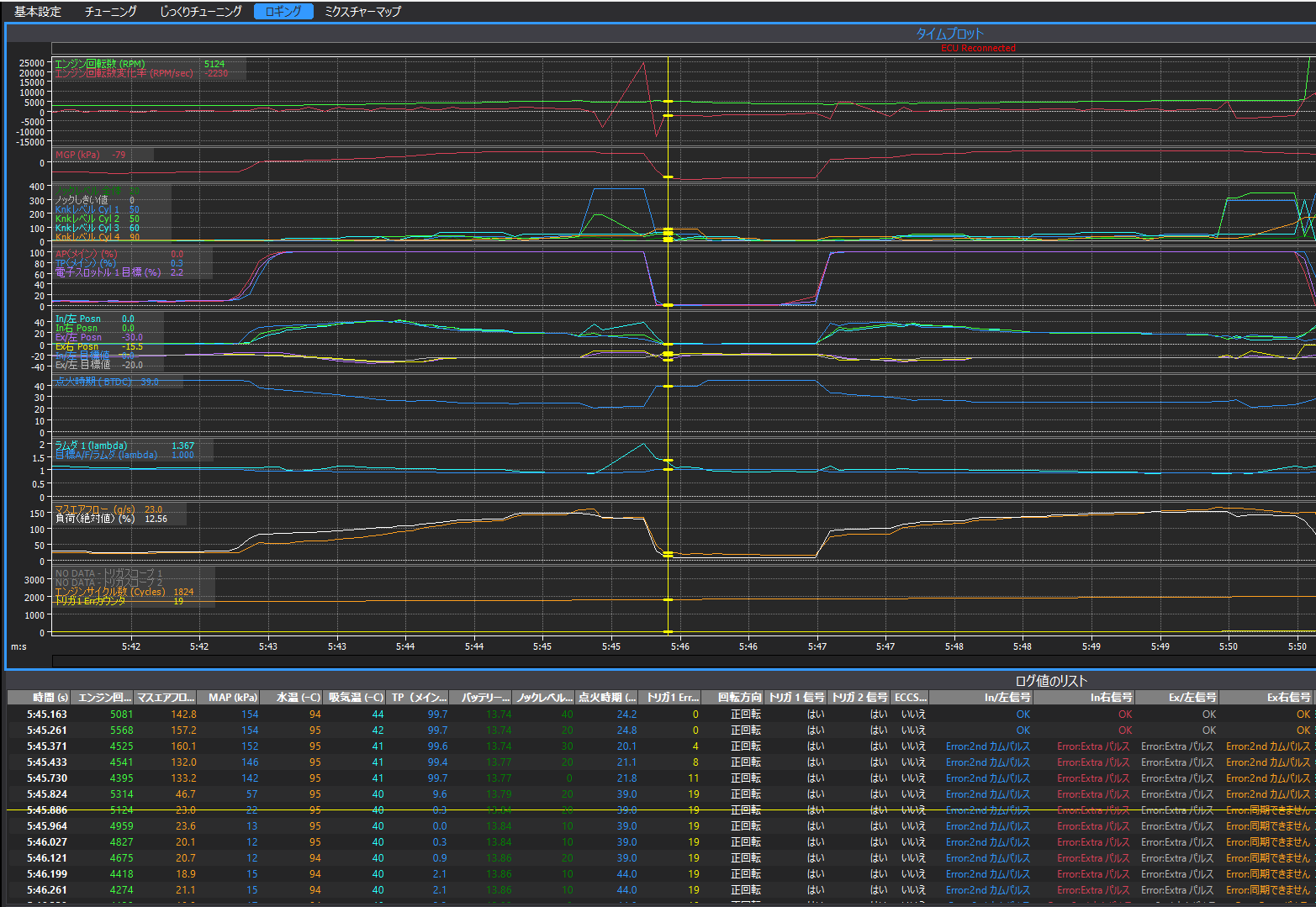

-
On 2018/3/8 at 10:10 AM, Adamw said:
The reason is that it is a 2011 STI, so it has significant CAN bus integration, certainly at least much of the dashboard is CAN driven and I think probably the "SI drive"/DCCD system will need CAN messages from ECU too. We dont do a plugin for years beyond 2007 so we havent reverse engineered the CAN and therefore our firmware doesnt have a "2011 STI" CAN bus mode.
Changing to V7-10 mode will not help. The problem is the cam signal inverting.
My thoughts are the inverting cam signal is likely to be due to one of the following:
- The piggy-backed OEM ECU is influenecing the signal. My next suggestion would be to try running the engine with pin A21 at the OEM ECU temporarily disconnected. It might even be a good idea to power the sensor independent of the OEM ECU.
- The sensor is faulty - that is why we suggested swapping L & R sensors, it is unlikely to have 2 faulty sensors.
- Maybe this signal inverting behaviour is normal/by design and is just something we havent seen before. However we know of quite a few dealers/users running this late engine without drama so I'm not yet convinced it is normal.
So my suggestion is first to try disconnecting OEM ecu (pin A21). If that doesnt help then the next step is to swap the sensors.
@Adamw
Hi
I have swapped my Left Intake Camshaft Sensor to a brand new one.
But I'm still getting trigger errors when RPM goes over 5000 rpm.
I have tried both, piggy back left intake camshaft sensor and also independent ( disconnected pin A21 from stock ecu and enabled pull-up for trigger 2).
I have also tried changing the trigger edge to rising too. but it didn't work neither.
So I think, the possibility you raised, which no 1 and no 2 could not be the reason.
What should I try next?
I have attached.
- the my settings file
- log file that I drove and tried to reach up to 5000+ rpm
- trigger scope around 900 rpm
- trigger scope around 2000 rpm. (only this looks weird )
- trigger scope around 3500 rpm.
- trigger scope around 5000 rpm.* all of these trigger scopes are collected in neutral gear.
Best RegardsPS.
Althow the idle is unstable, I just haven't setup the closed loop idle control correctly.
So please don't care about it.
Trigger Scope Log 2000RPM 2018-03-21 3;06;57 pm.llg
Trigger Scope Log 900RPM 2018-03-21 3;06;40 pm.llg
-
11 hours ago, neil brown said:
as an outsider to the thread looking in
why piggy back onto the original ecu when the link fury is more than capable running the engine and many other functions on its own
6 hours ago, Stevieturbo said:There may be legal/inspection matters that require the factory ecu to be in place ?
Thank you for looking the thread.
The reason that I choosed the piggyback instead of indipendent Fury.
Is because One is the CAN and DCCD.
Also, my engine needs a lot of output and inputs.
Like tumble generator, secondary air conditioning valve, charcoal canister, air conditioner system, e-throttle, power steering, inter cooler water spray system, input and out put camshaft VVT(subaru call this AVCS) etc...
So I need Thunder to support all of these input and outputs.
But I only wanted to control stuffs that makes more TORQUE and HORSEPOWER!!!
Thats why. thank you!
5 hours ago, Adamw said:The reason is that it is a 2011 STI, so it has significant CAN bus integration, certainly at least much of the dashboard is CAN driven and I think probably the "SI drive"/DCCD system will need CAN messages from ECU too. We dont do a plugin for years beyond 2007 so we havent reverse engineered the CAN and therefore our firmware doesnt have a "2011 STI" CAN bus mode.
Changing to V7-10 mode will not help. The problem is the cam signal inverting.
My thoughts are the inverting cam signal is likely to be due to one of the following:
- The piggy-backed OEM ECU is influenecing the signal. My next suggestion would be to try running the engine with pin A21 at the OEM ECU temporarily disconnected. It might even be a good idea to power the sensor independent of the OEM ECU.
- The sensor is faulty - that is why we suggested swapping L & R sensors, it is unlikely to have 2 faulty sensors.
- Maybe this signal inverting behaviour is normal/by design and is just something we havent seen before. However we know of quite a few dealers/users running this late engine without drama so I'm not yet convinced it is normal.
So my suggestion is first to try disconnecting OEM ecu (pin A21). If that doesnt help then the next step is to swap the sensors.
Thank you so much.
I will try the no1.
although I have already disconnected the pin A21 from the stock ECU.
But I haven't try the power and the ground from the sensor independent of the stock ECU.
Even that didn't fix it, I will change LH input camshaft sensor to new-new one.
Even the wage of swaping these sensors are expensive, The price of the sensor is not so expensive.
I'll change it to new-new one just in case.
Best Regards. -
@Adamw
Thank you for your reply.
Sorry for my misunderstanding.I asked the garages how much does it costs to swap camshaft sensor from left to right.
They said it costs around 20000yen (about 180 USD).
If it's possible, I want to check the other possibility of this problem first before I swap my sensors.
Maybe like, collecting the trigger-scopes at around 5000 rpm. Or anything else.Also My stock ECU has a diagnostic system that can notice the camshaft sensor errors.
I rolled back my ECU to stock to check if there is an error.
But my ECU doesn't notice any types of errors.
I think the waveform from the camshaft sensor doesn't change even if I change it to new-new sensor.I also took a log from Romraidar with my stock ECU installed.
But the engine RPM, camshaft position and any other logs does looks fine.
Any other opportunities?
How about changing the trigger mode to "Subaru V7-10(JDM)"?↑Sorry if I was saying something misdirected.
I forgot to say but I've already changed the trigger 2 pull up to disabled.
The trigger-scopes that I mentioned here are all collected with trigger 2 pull up disabled.
Also, I have my camshaft position sensor's ground connected to stock ECU.
Is that ok?
Thank you.
-
@Adamw @Simon
Thank you for your advice.
I have exchanged the trigger.
now trigger 2 is at Intake AVCS RH and DI1 ad Intake AVCS LH.
But still not working well.I couldn't start my engine.
I took a multiple trigger logs when I am cranking.
RPM was increasing and decreasing between 700 rpm to 900 rpm.
Could you help me solve?
one more question.
what trigger mode should i select?
I was trying with EJ 20 quad avcs.
is that ok ?
Thank you.Trigger Scope Log 2018-03-7 1;06;41 am.llg
Trigger Scope Log 2018-03-7 1;06;07 am.llg
Trigger Scope Log 2018-03-7 1;03;44 am.llg
-
I was reading the help browser in PCLink.
I found that there is a trigger errors in SubarV7-10.
Title is "Trig2: RPM Lockout".
```This functionality, specific to the Subaru V7-10 Trigger Mode, is to eliminate trigger errors in some applications.
This value specifies the engine speed (RPM) at which the ECU ignores the trigger 2 signal for synchronization information. Because the ECU is already syncronized this will have no effect on engine operation.
If you are not experiencing trigger errors, set this value outside the engine operating range. e.g. 12,000 RPM.
If you are experiencing trigger errors, a typical value for this is 3,000 RPM.
```I think my car is Subar Version 10.
Does this can be possible for this problem's reason? -
Hi
I noticed that both trigger scopes has same timing of when trigger scope 2 is falling.
Also these two trigger scopes are collected in different rpm.
My english is bad so I attached the picture what I'm trying to say.
I also attached an wire info.
Just in case if it will be an clue.
I forgot to say that my Fury is piggyback of my stock ECU.
I'll try exchange the Intake camshaft RH to trigger 2 tonight.
@Adamw
Could disconnecting Intake Camshaft position sensor from stock ECU could help?
Or the sensor's 5V(I guess) input is coming from the stock ECU.
Changing this from the Fury's 5V sensor voltage could help?
Sorry for my newbie.
I am realy happy that you help me.
Thank you so much!


-
Hello
I had a gear box trouble so I couldn't test until today.
@Adamw
I have changed the trigger 2 Edge as Rising.
But I still keep receiving trigger errors.
I feel it's getting even worse.
Also occures at around 1500rpm too.
I added the trigger scope at 1500rpm and the log I just collected today after changing triger 2 edge to rising.
Do you have any guess?
Thank you.
Log 2018-03-5 12;45;59 am-trigger-error.llg
Trigger Scope Log 2018-03-5 12;43;44 am.llg
-
HI, Adamw
Thank you very much for your advice.
I'll try that "Rising Edge" settings tonight.
Best Regards. -
1 hour ago, Adamw said:
Ok thanks, now I understand. You have massive trigger errors in all logs.
The next step is to do a triggerscope so we can see what is wrong with the signal (just at idle will be fine). Here is a short video how to do the trigger scope: https://1drv.ms/v/s!AiYbYlZQuRHPmieMTkwQDCXEb2LY
Please "save as log" and attach the file here.
Thank you so much Adamw.
I have attached my trigger scope log when the engine is idling at around 900 rpm.Best Regards.
-
I forgot to say that, if I swap to stock ECU.
Than the engine works fine up to 8000 rpm.So I don't think this is a mechanical problem.
-
Hi Adamw
Thank you for your immidiate responce.I have attached multiple logs and my pclr file when I collected my logs. (although I changed the ignition timing for test)
My engine is 8000 rpm limit at factory.
And my link ecu is set to 8000 rpm max too.
You can see that, AP(Accel pedal position) is at a constant value (or could be increased slowly) but the rpm increces and decreses crazy.Some times it shows like at 30000 rpm. but the noise from the engine doesn't sounds like 30000 rpm. (not 3000rpm. 30000rpm lol)
Best regards.
-
Hello
Thank you for your attention.
I need help with my Subaru WRX STI 2011 JDM EJ207.
I have implemented my Link G4+ fury with my car.
But my engine does not increase rpm more than 5500rpm.
Under 5000 rpm works fine.
I've tried changing my ignition timing from 45 BTDC to 0 BTDC but it does not have any effects.
I've also double checked my dwell table, Ignition delay, Ignition charge time as same as shown in help in PCLink that it's same as the EJ20 quad AVCS configuration.
Do you have any guesses? Thank you very much.


EJ207 VVT Settings
in G4+
Posted
I have tried changing both clamp table and proportional.
It went pretty well on the exhaust right cam. but not on left cam.
I have swapped to the stock ECU and took some logs. but both right and left exhaust cam were stable.
I think it is not a mechanical problem.
Should I use separate PID settings for right and left exhaust cams?
And do you have any idea why does my left exhaust cam are going up and down.
https://drive.google.com/open?id=1AjfPYF8nR7Jw-arvEXf-mMwlgSiQ4q1u
https://drive.google.com/open?id=11oXq1Vj5YbyYr2Lu0Oi89E_y6qlxHNX5