


airjer
-
Posts
12 -
Joined
-
Last visited
Content Type
Profiles
Forums
Events
Gallery
Blogs
Posts posted by airjer
-
-
Nevermind, I figured out a way.

-
No clue what you mean on either account.
Any chance you could explain this to me?
nevermind, my 3rd time searching the help file I think I've found my answer

-
what does polarity high or low mean? does low mean negative and high mean positive?
what does Driver type high side or low side mean? Is this High or low resistance like a injector?
-
8 hours ago, cj said:
The COR is best thought of as a traditional fuel pump relay - ECU grounds pin 4 and the pump turns on. No ground here, no fuel pump.
OK, so fuel pump control via FC wire wired into ECU for fuel pump control. That's what I thought! Thanks.
8 hours ago, cj said:The dual position relay marked FPR is a high/low switch for the fuel pump [if its enabled at all by the COR]. on 1x path it runs via a big resistor so the pump sees less voltage. Given you have probably completely rebuilt the fuel lines anyway to run the bigger engine, i'd ditch the FPR relay & wiring and run the COR as simple on/off fuel pump control. Exactly how you do this is up to you but on factory wiring i'd just join the 2x wires going into the big resistor together so that it doesnt matter which position the FPR relay is in.
I think I had already bypassed the resistor when I had the turbo engine, I suppose the Fuel pump relay is redundant and can be eliminated
8 hours ago, cj said:Ac...the biggest problem with AC in these is that most of them were built for R12a refrigerant which you cant buy any more. Assuming you re-do all the seals for something R134a compatible then you can get started. If you dont sort the seals on the whole system, it wont last very long before it starts leaking gas and you have no cooling.
I own a heating and air conditioning company, and I can buy Virgin R12, I can literally go into the supply house and buy it. They still have tons of it. I have a 30lb jug of R12 at my shop. I already bought a new compressor, new drier, condenser, evaporator coil, expansion valve, and flex lines. everything but the flex lines came from Denso, so they are OEM items.
8 hours ago, cj said:Lets say you got around that though.... the igniter input to the ac amp is just to switch off the compressor at high RPM. The link ecu can do this for you anyway so just leave it disconnected. You wont have a high output ignition coil feed to run to it anyway on a modern engine. The factory wiring is set up so that when the AC amp triggers the clutch to engage you'll see +12v on the black/white wire at the ecu as well, so this can be your idle up signal to the ECU. There is also an ACA/AC1 pin from the ac amp to the ECU which is grounded by the AC amp when it requests ac compressor operation. You probably only need 1x of either this or the actual compressor engagement signal. The pin labelled ACT is the signal from the ECU to the ac amp to cut ac operation. The ECU grounds this pin to request AC cut.
So let the AC Amplifier control the ac and just input the solenoid wire black/white to the ECU for idle up.
8 hours ago, cj said:As @Adamwsays, you have an option to drive the AC compressor relay directly from the ECU - and the pressure switches are in line with the relay feed so you dont worry about those. You would also need to run the pink wire from the controls to the ECU as an ac request. Depending on how much re-wiring you've done i'd say its probably a touch easier to use the amp though - that way you dont need to re-wire the fans to a radiator switch or the ECU (factory fan circuit is separate from the ECU but uses the AC amp to read radiator water temp). You trade 2x inputs (a/c amp version) for 1x input & 1x output if you move to ECU controlled AC wiring, but you more than likely also need to use an additional output for radiator fan control too. That might be good or bad tradeoff depending on what pins you have available.
Definitely going to rely on the AC amplifier to control the AC.
Thanks for explaining how the ac amplifier works.
-
Adam,
The SW20 has a COR and a fuel pump relay that is a 2 speed relay essentially. When on it will default to sending power thru a fuel pump resistor for low speed fuel pump operation (NC set of contacts) and then switch to High speed operation when needed. I would like to utilize the factory fuel system wiring as it is apart of my body harness. The problem I am having here is that the factory ecu would cut the fuel if the engine dies. This is a important safety feature if you were to get in an accident. I would like to retain that type of functionality, is it possible with the fury ? Correct me if I'm wrong but loss of ground to the COR should open the fuel pump relay and kill the pump. I have attached the snippet of the diagram that shows it. Looks like I'm going to abandon the blue/red FPR wire, and bypass the Pump resistor. I have my own relay under the center console that is triggered by the factory fuel system wiring and just connects power from the battery directly to the pump as the small gauge and long length of the factory wiring has quite a voltage drop by the time it reaches the pump. So then I could just use FC wire and wire it into the Fury on a AUX output for fuel pump control. Also Toyota has a built in circuit for priming the pump, or at least running it while your cranking... The Start wire from the ignition switch energizes a secondary coil in the COR to run the cor while cranking.
I will take the existing AC input to the original ECU and wire it up as a input on the fury. that way the ecu knows whats going on, and can perform idle up. Going thru all the wiring diagrams the only pin that goes to the ac amplifier thats at all related to the engine is the IGN ignition input on the A/C Amplifier. So I hope that input is not critical to have for the ac to work.


I also started putting together a basic configuration on a sample base map just to familiarize myself with how it sets up. I've been logging alot of what I'm doing in a excel sheet for reference.
-
Thanks for the replies guys. Looks like I'' be using the dash to bring in one of the front wheel speed sensors and using the vehicle speed sensor off the trans to feed the ecu with driven wheel speed.
So with that sorted, I'm looking at my chassis side wiring as some mainly power circuits need to be integrated into my engine harness.
- So I've found how to wire the starter relay circuit, is it wise to give the ECU an Starter input, or is that even necessary, since it will have input from the crank and cam sensors to know when it's being cranked.
- My chassis uses a Circuit opening relay to power the fuel pump relay. The fuel pump relay is triggered by ground signal from terminal FPR from the original ECU, and has a Fuel Cut function on the circuit opening relay which is fed from terminal FC on the original ECU. What is a sound way of controlling this using the Fury? It seems that I could take both functions that the toyota ECU performed and use one AUX output to ground both relays at the same time. But I'm not sure what control logic could be used in the fuel pump control built into the Link fury. Help?
- I'm assuming all 4 cam sensors, and all 4 VVT solenoids need to be wired into the fury for VVT to work correctly?
- I also don't know how I'm going to approach keeping the air conditioning working. I have a brand new 1GR compressor which is a simple compressor 2 wires to a ac clutch.... But my chassis uses a ac amplifier, and it has a input from the original ignitor for some purpose. maybe to verify the engine is still running the terminal is called IGN Not sure if it's necessary to have or if I just have to shut the ac off before trying to start the engine so that I don't have the increased drag of the compressor.... I'm not sure that it would even be worth having the ecu control this and lose a input and output.
-
I have a built 4 liter stroker 2GR engine I've spent the last 7 years building, I have finished my headers, and fabricated a custom intake manifold. I am using the Toyota DBW pedal and a GM DBW throttle body. I have made a chart and started labeling all my wires, and grouping them together for particular sensors, etc... But I've noticed a issue.
I want to have the following features
- VVT Control
- Launch Control
- Anti-lag
- Boost Control
- Cruise Control
- Traction Control and Boost control by slip %
- Intercooler pump control
- chiller control based on temp input of intercooler water
- ac compressor kill
- Flex Fuel with fuel pressure input
- and maybe more
but i've noticed I quickly run out of inputs and outputs.....
I also have a Link/AIM street dash.
So I need driven wheel and non driven wheel inputs and everything I've read shows needing all 4 wheel speed inputs and it just doesn't look like I've got enough digital inputs.
Any chance I can use the AEM 22 Channel CAN sensor module PN 30-2212 to add the 4 wheel speed sensors?
Also I am compound turbocharging this engine to acheive a smoother power band, reducing lag, and keeping the turbos in their efficiency island. which complicates the boost control...
-
35 minutes ago, cj said:
At full throttle no, but at part throttle you can get some reverberations, EGR effects depending on VVT timing and cam overlap, and the IAT can read higher than it should because of this. It can also get damaged by fuel mixture floating around in the throttle body.
That make sense. I will put it in the throttle body if there is enough room, or Ill weld an extension onto the throttlebody so I dont have to place it in the intercooler piping.
-
20 hours ago, Ducie54 said:
Do you have any pics of your setup? Curious to see how you have setup the slushee evaporator.
In my water tank I added another tank inside to fill with dry ice. I also have IAT sensors both side of the water core to measure temp drop across the core.
The more water flow you have the better I found.
I don't have any pictures of the slushee evaporator but it's very similar to this https://fiinterchillers.com/products/
The Jabsco Cyclone Centrifugal pump flows 30gpm and I have a heat exchanger at the front of the car, and the resevoir and everything is in the trunk.
16 hours ago, cj said:The recommended location of the IAT sensor is after the turbo + intercooler, just before the throttle plate. This way the ECU has the best idea about the actual temp of the air entering the engine. If you install additional sensors you can view them in log files etc but they will be for your interest only and wont participate in the actual fuelling calculations.
I had actually planned to put the IAT for fueling calculations behind the throttlebody in the intake manifold. is there anything wrong with putting it there?
9 hours ago, Adamw said:I would consider adding an idle valve if it were me. Although you can control idle with DBW as CJ suggests, with a 102mm throttle on a 3.5L engine it is not going to be great idle control.
It's actually a 4.0 Liter Engine, I am using a modified 1GR crankshaft. But still I thought it might be needed to smooth out the idle.
-
I was thinking of using a air temp sensor before and after the intercooler. To see the efficiency of the W2A intercooler and my chiller. I have a r134a Slushee machine evaporator inside my intercooler tank that keeps the intercooler water chilled to 40 degrees.
-
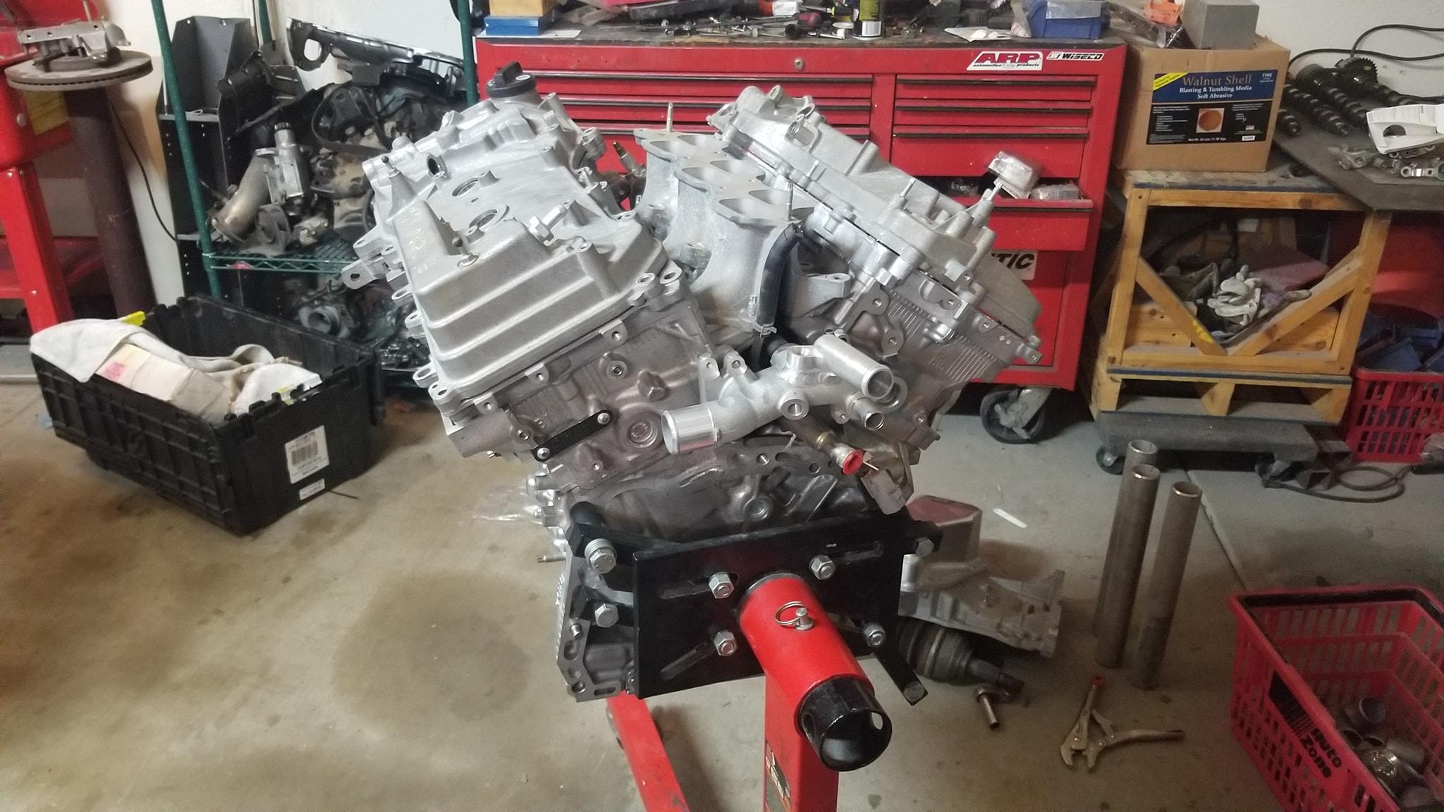
I'm extremely close to finishing my build and trying to get this thing running. This is the setup.
- Brand new Toyota Shortblock closed decked and re-machined
- 2007 Avalon 2GR heads
- Custom Wiseco pistons
- Custom BC Racing Rods
- ACL Race Bearings
- Shimmed Oil pump
- Custom Manley Sodium filled Stainless Steel 1mm oversized valves
- Custom Manley Valve Springs to match new valves
- Ferrea Titanium Retainers
- Custom T-11 Tool Steel Lash caps
- Stock Cams for now
- Moroso Oil Pan
- Radium Fuel Rails
- ID2000cc injectors
- Holley EFI Hi-Ram intake manifold top 300-219 bolted to the 300-217 Holley HI-Ram Manifold top and all this bolted to the factory lower plenum
- 102MM GM LS Drive by wire Throttle Body
- Toyota DBW pedal
- 1.5" Stainless steel steam pipe ells primaries to 2" V Bands with a 2" Ypipe into a T4 Flange
- (2) Tial MV-R Wastegates
- Borg Warner S366 SXE Turbocharger
- Custom Water to Air Intercooler
- Jabsco Cyclone Centrifugal pump
- Methanol Injection/Water Injection using Shurflo pump
- Planning on running E85/Flex Fuel
- Link G4+ Fury
- Link 6.5 Bar Map Sensor
This MR2 has Air Conditioning, Cruise Control, ABS and Power Steering. I'd like to keep all this functioning. In addition I'm curious if there is a way to use ABS and the Throttlebody.
What I know I dont have so far and need/want to purchase
-
Ethanol content sensor - Intake Air Temp Sensor
-
Fuel Pressure Sensor -
Oil Pressure Sensor - Manifold Air Temperature Sensor
- (2) LSU 4.9 Sensors
-
Boost Control Solenoid - Link MXS Strada dash
-
Oil Temperature Sensor
I'm pretty sure I can use my factory Coolant temp sensor. My Throttle body doesn't seem to have a idle air bypass like a Toyota throttle body would have, also I don't have a AC Idle up valve.
So I'm trying to figure out what all I need, and make sure I'll have enough input/outputs for everything. If anyone has suggestions of which sensors to use, and links to the best deals that would be awesome. Any tips for setup? Any links to High quality loom materials, motorsport quality stuff.
If there is anything you guys see that I may be missing out on, please drop me a suggestion.
Thanks in advance for any help.


Wiring in my fury on my 93 MR2 2GRFE TURBO
in G4+
Posted
So this car has sat since November 30th, 2019
I just started to try to complete the wiring on the car yesterday. The long hiatus was due to a fire started by a neighboring suite that burned my business down. The laptop that had my notes and diagrams and everything was destroyed in the fire. Finally after 4.5 years I decided I need to finish this car. Luckily I came here and found my notes, and my spreadsheet. Otherwise I would have had to start all over. trying to log what I had planned originally.
Thank God, I uploaded it here!
I spent all day yesterday wiring what I knew and building a new fuse box that is smaller than the factory Toyota fuse box so it'll fit in the trunk behind the carpet!
Hopefully I can finish the car and have it running before the summer heat hits.