Dhornby88
-
Posts
45 -
Joined
-
Last visited
Content Type
Profiles
Forums
Events
Gallery
Blogs
Everything posted by Dhornby88
-
Spoke with tech support on phone today Adam, it turned out i had +/- at motor around back to front at throttle body. Seems to be operating now, Thank you LINK team.
-
Did I need to clear the fault codes? With the motor whining, could the whole issue be the +/- be back to front in the wiring at the throttle body.
-
no it doesnt move, it just makes the whining electrical noise from the throttle body, ill attach a couple logs I took when I manually opened the throttle body blade by hand and also depressed the accell pedal. e throttle logging 2.llg e throttle motor whining.llg e throttle log test.llg
-
https://www.dropbox.com/s/xasgqf6vure5ee7/Video 10-1-21%2C 7 39 28 am.mov?dl=0 see attached video from my dropbox
-
I attached picture above?
-
-
https://www.golebysparts.com.au/products/bosch-electronic-throttle-body-68mm-bore-0280750156?variant=15659837194349
-
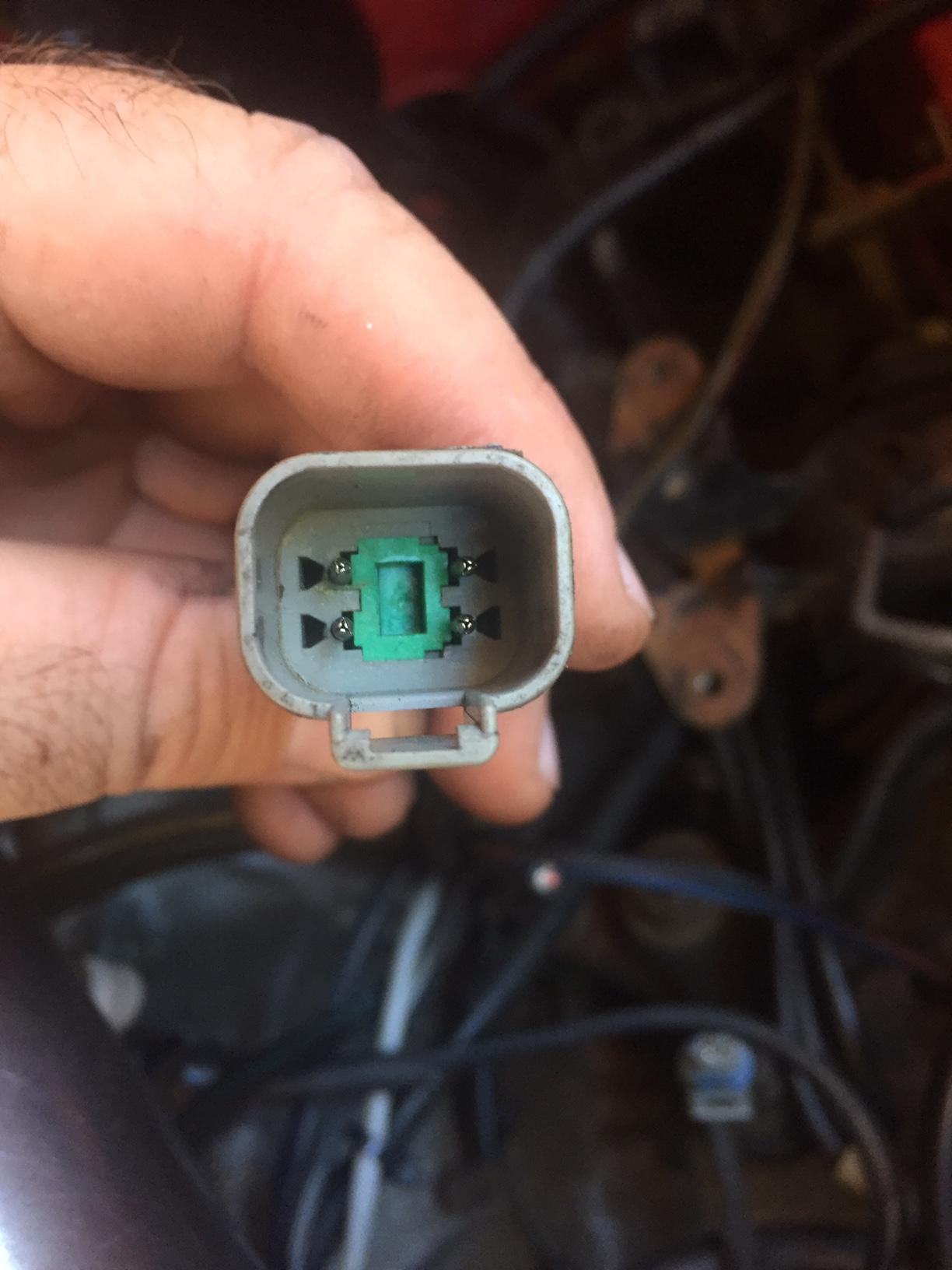
ill draw another diagram now. The pedal is VE 6 litre GM unit Is it normal for the module to be piping hot? The ecu you can see in video the tps and pedal are reading voltage that seems right?
-
Its been pinned into pin 1 that didnt work even when called e throttle relay. Then attempted PIN 48 AUX IGN3 and 37 AUX3 both made no changes still doesnt work, the module gets piping hot very quickly. Should e throttle signal 2 be turned on when number 1 signal is also activated. https://www.dropbox.com/scl/fi/160mgyfdzgtkmg6jzul8f/IMG_4929.MOV?dl=0&oref=e&r=ABSw5Kij0BzInE3paEMVOfOcp42YVpaFhADLUgvnD3koV-f74W8J-X3vCvapeRSLjvJJvRRR56CswJfVS8n4csdEfdJJP5B1MTQWYHjJusjDInpP5G275lHEc69InFnXot5dzYPaHlQcoFtlaqtW5MtNut_RuYNVS6IDBKmALoUL-a19rOwyaukLXGBJ_K-9piQ&sm=1 you can hear it making a strange electrical noise at the end too.
-
Thank you Adam, ill see how i go. Regards
-
Hi Please see where i'm stuck with the conversion, excuse my diagram i did the best i could. Am totally stuck with doing the pedal but i'm unsure if i'm going down the right track with the diagram anyway, can i have some feedback offered? Regards

-
Hi Team I have a AEM UEGO gauge part 30-5130, since the ecu install its reading on gauge but cant get it to work through the ecu, I have currently selected LAMBDA 1 on ANALOG 9, see images below where i wired it too, i also used the expansion harness to supply the other 5V. Have i possibly wired it up to wrong parts of the expansion loom? Thanks


-
-
Hmm thats possibly for knock sensor, as the knock control unit it right next too it, and yes the injectors still click when its unplugged. good point. regards
-
Thanks Adam, Bypass the resistor leave it un plugged? or cut the plug off and twist the wires together and solder? Thanks Daniel
-
Hi Adam, Simon Seeming to have an issue where i can only get 2 injectors firing when i perform the test, ive swapped the injector loom, swapped plugs and checked if they are blocked and still cant get it to work. I thought it was due to the factory GTX harness runs a resistor pack. I tried with it plugged in and unplugged no change. I have high impedance injectors. Ive gone into injector mode tried with sequential and multi group too. Could you assist? I dont know what easiest using team viewer or facetime or skype? Can be difficult to be thorough writing a message online I added images to my thread you were messaging me on if that helps? thanks

-
Hi I tried to run an injector test and only cylinder 1&2 are clicking, 3&4 nothing. It’s on setting sequential, they are high impedance injectors, but I did leave the factory GTX injector resistor pack unplugged. Injector setting was on sequential, did test that they are clicking with direct power to injector off the battery. another question regarding using AFM wiring at the plug, do I just take the 1 signal wire at AFM unpin and run that to the Airtemp sensor? And earth the other side? Or do I run the other wire back to the expansion harness? See images below.


-
Thanks for that input, and the link boost controller, what would you suggest I do with that? the stock solenoid is controlled by the second trigger I would use for the coils. or can I use expansion harness for the boost controller?
-
I purchased the Link boost controller and i thought id have to use PIN 1H, but that would be my second trigger for the coils? would you suggest i splice into the wires? or should it unpin from the main harness? can i then use the expansion harness for the boost controller? regards


-
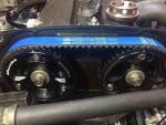
Hi Purchased my first link product, G4+ plug n play for my Ford Laser running a GTX/GTR 323 engine and factory harness. Had a few queries im unsure about -fuel pump trigger relay, I have a walbro 460 so have ran fatter wiring and relay, factory set up i had a wire ran from ignition triggering the relay and turning on the pump. But i was hoping the link would do this for me, do i use an AUX 7,8 to trigger the relay to turn on pump from the expansion loom i purchased? -dizzy swapping style to coil on plug, i have purchased some coils that have inbuilt igniters, 4 wires are running from the coil on plug wiring i received, guessing 2 are trigger for the waste spark other 2 wires one is ground and 1 direct ignition power? see images below of the coil side of the plug i have -tachometer converting to coil on plug my tach wont work? i do know where the negative of the coil is on my factory harness i think thats what sends the signal to the dash, how would i get a tacho read when converting to coil on plug -should i purchase 2 expansion harness's? as i noticed in the manual expansion connector one offers temp sender output that id need for my link air temp sender? but expansion 2 that has what i need for wideband control (aem uego i have) and the coil on plug setup plus fuel pump. Hope it makes sense some feedback and pointers would be appreciated with the install, ill possibly attempt to get the car running on the standard dizzy for starters then add coil on plug at later date? Regards Daniel