


Mario Schneiderbanger
-
Posts
35 -
Joined
-
Last visited
-
Days Won
1
Content Type
Profiles
Forums
Events
Gallery
Blogs
Posts posted by Mario Schneiderbanger
-
-
if his tps isn't working is it pegged at 100% by chance? possible the tuner setup a flood clear table when tps is 100% with engine off?
-
adam, by setting the cll lockout to 1600 you are effectively disabling cll at idle always.
can't we set up an activation delay where if there is a change in tps the cll waits say 10 seconds before engaging? that way while backing out of the garage or inching up in traffic, as soon as there's a delta TPS logged it disables cll and waits 10 seconds or whatever you want before it activates again?
this way it won't try to reduce fueling while you're puttering around but will engage if you are sitting in a parking lot for a while
-
check the realdash thread at the top of the page. I just posted a can bus how to that explains how to set it up
-
Alright over the next few days i'll put together a how to on getting Real Dash to read data off the G4+ using a Seedstudio Can-Usb adapter. This way you can tap into all the available data including lambda/Ethanol% and whatever else that the serial stream doesn't support. With help of another forum member i've stumbled my way through this and now have a working gauge setup on my android tablet. 3 days ago I had no idea where to start with this and i assume other users probably feel the same so I'll share what I learned.
This will include how to:-wire the adapter
-connect it it to realdash
-write the xml file
-try to explain how to use the can calculator to make sure your conversion are properly setupWhen all this is done you can even display it on a android enabled radio
First thing to do is wire the can adapter into your Can 2 output on your B plug. I chose this route because i didn't want to buy the connector required to tap into Can 1 under the tuning port. The adapter also needs a single ground wire going to chassis "sensor ground would probably be fine too"
next you're going to want to open your CAN setup in your PC link file and select Can Module CAN2.
Mode will be User defined, but rate 1Mbits and OBD set to off.Under Data you will see 6 available channels. Each of those channels will be set to 1 can stream on the next page. Each Stream can hold 64 bits of data. Some parameters are 16 bits and others only 8. It tells you when you select them. More on that later.
Click channel 1 and under Mode select "Transmit User Stream 1". Transmit rate is 200hz. Under CAN ID set ID to 1001 "you can put anything you want but you'll see why I did 1001 soon. Once this is done go to the streams page.
Click on Stream 1 and then "Add frame" then click on "Frame 1" and then under parameters click "add"
Look at my example photo. Lambda has a width of 16 bits "2bytes" but ethanol % only has a width of 8 bits. You can either have 4 parameters each 2bytes or 8 parameters each 1byte or a mix of both like me. Once you fill up stream 1 with 8bytes you have to click on stream 2 and add another frame and keep going till you have all the data you want.
If you have 2 streams or 3 streams or more you have to go back to the first tab and assigns stream 2 to channel 2 and set the ID to 1002. same with stream 3... "now you know why i named the ID 1001-1002...."
NOTE: WHEN SELECTING THE PARAMETER YOU WANT BE CAREFUL THAT YOU DONT SELECT THE AN VOLT VERSION OF THAT PARAMETER FOR EXAMPLE AT1 and AT2 FOR ECT/IAT WILL OUTPUT THE SENSOR VOLTAGE AND NOT THE TEMPERATURE.
We're done in this window. Apply and Ok out of the window. Store to ecu and save
tomorrow i'll explain how to get real dash to now read the incoming data that you just sent out in this menu.
Take a look at the screen shot of my XML file. After <Frames> you will see the beginning of the data stream. frame ID 1001 is Channel 1 aka Stream 1 from the CAN Setup menu. Notice that the parameters under frame ID 1001 in my xml file match the parameters in my can setup under stream 1-frame 1.
This is where it gets a bit tricky. Target ID means the address in realdash you are sending the data to. in other words when you create a gauge in realdash it's going to ask for a data source. You then pick from a list of channels and in order to figure out which channel is what ID you use the link here:
https://realdash.net/manuals/targetid.php
Target id 254 is Lambda 1 under Engine/ECU Inputs and that's what we're going to use.
Next is the offset and the length. Look at the can setup. Lambda 1 has a "Start Pos" of 0 and a "width" of 16 "remember 16 is 2bytes"
Ethanol% then has a "Start Pos" of 16 and a "width" told 8 "1byte"
this makes sense because if lambda is 16bits then the next parameter has to have a start pos of 16 and if ethanol is 8bits wide then the next parameter has to have a start pos of 24. So far so good?
Now in the XML file we don't use bits we use bytes so for Lambda the "offset" <----start pos will be 0 and the "length" <----width will be 2
For ethanol% the "offset will be "2" and the "length" will be 1
Which means the next parameter would have a offset or 3.....
eventually you will have all the parameters on stream 1 in your xml file and then you need to tell the xml file to start looking in stream 2. you can see that where frameid 1002 starts.
After "length" you will see some parameters require a conversion in order to display properly. You can go to the help file under CAN examples and look for the conversion method and then under can setup try it out in the can calculator. This was the most confusing part for me and i don't really know how to explain it well. Maybe Adam Walmsley can help. It was trial and error for me.
Once you have the xml file built you save it to your tablet in the realdash folder and now we go to setup realdash.
Open realdash and go to your garage. open the door of the car "click on it" and then click on the gauge cluster. This will open a menu where you can add connections. Add a can/lin connection and go through the options. make sure your tablet is connected to your can adapter during this step. At the end it you will see a button for picking a custom can configuration file. navigate to the real dash folder and click on your xml file.
once that's done leave the garage and either pick a theme or make a custom page and start setting up gauges. Now you have to assign the gauges you want to use a data source. So hit edit and click on the gauge you want to use. Click inputs and navigate the list to get to the input associated with the Target ID you chose in the xml file. Use the target ID page i posted to help you navigate.
There's some info on how to do that part in this video. https://drive.google.com/file/d/1_ynfTPGEdv66t1SfTVrf1hsk6QOM3AkX/view?usp=drivesdk
I'm sure i forgot some things so if you get stuck anywhere let me know and i'll help.

can't upload any of my screen shots because of the image size so i'll update this when i reformer them

-
got mine working via can adapter today. i assume this will work for g4x as well. If anyone wants to set this up order one of these and i'll post a step by step to walk you through it
https://www.seeedstudio.com/USB-CAN-Analyzer-p-2888.html

-
following since i have the exact same issue on my car and also running 1700x with e85
-
On 5/23/2020 at 6:21 PM, SchuKingR said:
just download my files from the post above and then swap out the "<frames...>" for the "<frames>" and you are good to go. I can't explain it to you more, because it's not very easy for me to describe something complex like this 1. by text and 2. in english. But it's simple, just try to read my xml file and look at the pcl CAN settings and try to understand
")
Ach na dann halt auf deutsch
 melde dich mal auf whatsapp +1 (727) 485‑6673
-
13 hours ago, SchuKingR said:
Found it!!! You only need to delete "<frames baseId="1520"> and only write "<frames>" in my xml file. Then it works perfectly
Thanks @Adamw! Your hint was the little thing, that pointed me in the right direction.
soooo how did you make this work because I see it displays lambda
-
great idea! What i need to do is use 4D for my high cam fuel map so i can turn on multi fuel mode. i'm currently using ve#2 for this which i'm pretty sure is reserved for the blend ratio table to work in multifuel mode.
maybe then my ve numbers will drop because some other e content based calculations become active. if that still doesn't work then i'll just do what you said and use a 4d table to pull fuel
-
On 4/18/2020 at 5:43 PM, dx4picco said:
So theoretically if the VE table is good and the warmup enrichment is off, i should have lambda 1 at cold engine too?
I have a similar issue which i'm thinking is charge table related but i haven't been able to nail it down yet.
I Also have my warm up table zerod out. Cold start "even with post start fuel zerod out" is .78 lambda and slowly increases to .95 target by 180F
I didn't understand how it could be charge table related as the IAT and ECT are the same for maybe 30-60 seconds after engine start unless the VE table numbers in my idle areas are higher than they should be BECAUSE my charge table is setup incorrectly for idle and therefor it's over fueling while cold -
Any way to display event logs like when you hit map/rpm limit or a engine protection limit?
Also, if i want to display map pressure do i chose MGP even tho i don't use MGP as a load scale in pclink?
And i take it we still can't display the fury internal lambda values?
-
does this work with real dash for IOS yet? if not what small device do you recommend for me to buy?
-
On 9/30/2019 at 2:42 AM, Adamw said:
30% eth @9:1 with 70% petrol @ 14.4:1 would give you a stoichiometric ratio of about 12.78:1.
Density will be about 0.758.
Hey adam, i’m in a similar boat but i’m running 60% mix. How did you calculate this? i’m currently switching to modelled mode from traditional and i don’t know what to set as the stoich ratio/density for my fuel
-
See this post. Right now that’s the only way to do it. Another member is working on a small wire in board that will take ECT info via can and output the 5v signal to the cluster
-
On 10/22/2019 at 11:45 AM, Richard Hill said:
USB extension cables work fine. I have also had success with USB over WiFi using virtual here.
I’d like more info on this usb over wifi so i could just mount the module under the dash and never have to pull it out.
thanks!
-
Can’t say enough good things about Link tech support!
-
Were in business!


-
Gonna give this guy a go


-
thx adam!
-
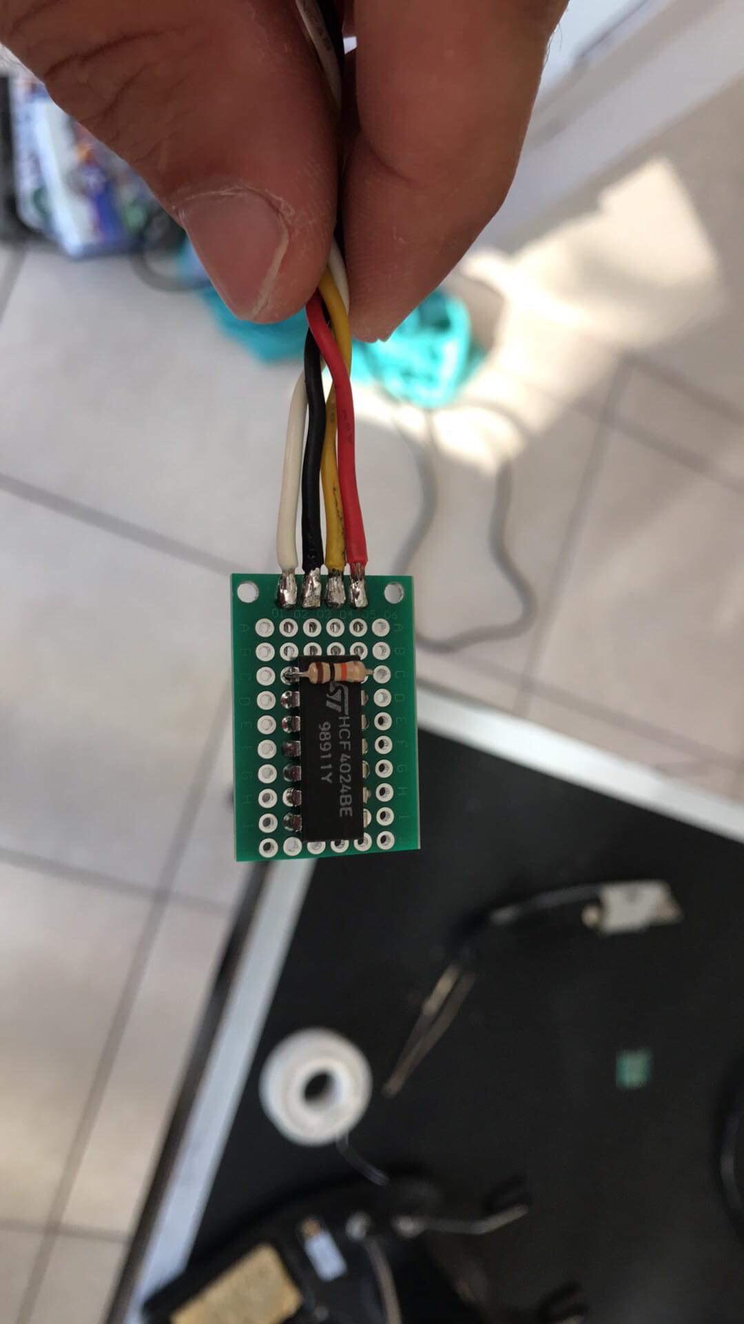
my circuit building knowledge is very slim.
can i feed 12 into the VDD (14) or must i feed it 5v?
ground goes to VSS(7)
My sensor signal goes to pin (1) and my output i’ll have to try Q3(9)
i’m also not quite sure how to calculate the pull-up resistor value for the VDD side

-
Thanks Rich, i realized after asking about DI11+ that my Fury doesn't have them. Any idea where I might find a divider circuit that I can configure to divide by 39?
Edit: It only needs to divide by 6 or 8 to get the full resolution
-
I dont think I can use DI1-8 for an ap1 s2000 speed input since the frequency is much higher than that of other sensors. Here is a chart i found. At very low speed it works fine but anything faster than 20 mph the reading goes erratic reading as high as 1500mph at times. Any suggestions? I already tried to switch from rising to falling. I have not tried the pullup resistor since it does read speed.
EDIT: I just checked the runtime values on DI3 and it reads up to 1600hz reliably before it starts to drop out. Unfortunately 1600hz is only 34ish mph which coincides with the chart below.
VSS Signal:
speed(MPH) S2000(hrtz) Integra(Hrtz)
0 0-100 0 0
10 500 15
20 940 26
30 1340 38
40 1800 48
50 2230 59
60 2640 70
70 3090 8080 3500 91
90 3910 101
100 4310 112
110 4810 123
120 5240 134
-
Adam, would it be plausible to:
- use the ap2 trigger wheels “cam&crank”
- switch to k20 vtec trigger mode
- but keep the trigger type on Reluctor
this eliminates the need to add the additional wiring for the hall sensors.
The only issue that may cause is that the tooth width isn’t optimal for a reluctor at which my next question will be what if i had a custom trigger wheel made with the same tooth width as the ap1 wheel but with the addition of the extra teeth
-
thanks adam! i’m going to try the less invasive “remove 2 of the cam trigger wheel teeth” first to see if it helps and then if i’m not happy i’ll swap everything over to hall and k20 mode.


 melde dich mal auf whatsapp +1 (727) 485‑6673


Introducing RealDash - A Dashboard App for Android & Windows
in G4+
Posted
EDIT: It’s an iPhone thing. On windows and android devices there is a minus sign on the keyboard that pops up when you click on a box. IPhone version doesn’t. Will have to ask realdashDev about it
How are you guys getting “- value” on your MGP gauges if the “MIN” section of value ranges can’t be set to a negative number? The “-“ sign doesn’t pop up as a selectable option on the keyboard when you click on a box. if I start off with something like “Boost PSI” as the data source which defaults to a negative number it changes back to 0 as soon as I change the data source back to LINK: MGP