iceman
-
Posts
33 -
Joined
-
Last visited
Content Type
Profiles
Forums
Events
Gallery
Blogs
Everything posted by iceman
-
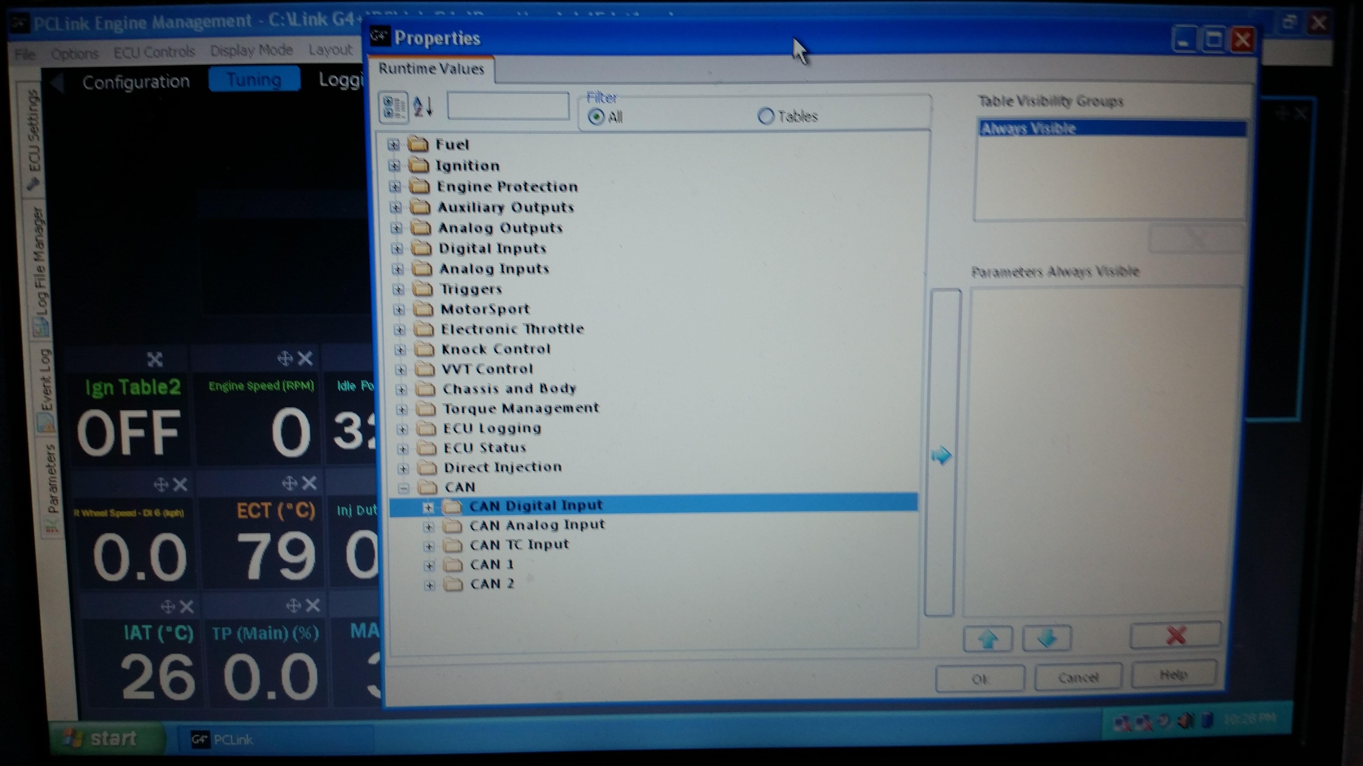
Richard, Simon, Thanks for the quick replies. As Richard suggested, I had a senior moment with the can hi and lo ECU input wires crossed and now have the can lambda device showing. I've saved the settings and cycled the power. Next question is how to get the can lambda WB reading as a digital qauge (prefer in AFR units) showing on my tuning dashboard. Looking down the runtime values choice list, the CAN folder shows at the bottom but which actual parameter out of the 4 Can sub folders do I select for the gauge to read? Thanks again. Pete.

-
Hi, Finally went to a Link can lambda WB device to replace an older PLX analog type but having problems setting it up. Followed the instructions from the Can lambda manual on the Link Electro website and have studied the subject matter on PC Link help pages but can't get my Storm G4+ wire in to "find" the Canbus device as per part 6 of the programming instructions. Phone pics of the Can setup/mode and Can setup/can devices pages from PC link attached, the latter indicating the Can device cannot be found. Also pic of the G4+ wire in ECU header connector to can cable being used. Only difference is that I've wired on an aftermarket inline 2 pin plug/socket connector to the Can hi and low (green and white) wires instead of fitting the original connector pins shown, into my ECU header plug. This new connector wiring is proven. Running 5.6.4.3240 firmware Confirming I have power and earth to the can lambda device. Where am I going wrong? Cheers.


-
Old thread I know but to result it for others, Nissan Z32 300ZX running a Storm black, the above circuit works perfectly in converting the Link ECU "speedo" DC output to an OEM AC wave form in order to run the OEM speedo. From this forum lurker, excellent support, Cheers.
-
Hi, G4+Storm running a Nissan VH45DE(+T). Engine has been running on a rough initial starting, warm up and idling tune only. Went to recheck the trigger calibration with a timing light while idling at normal temp and found the engine running slightly advanced by approximately 3 degrees from my initial calibration set up. However when putting the engine in "set base timing" mode another timing light check shows the timing marks (15 degrees BTDC) spot on again?? My first question is do I just leave the offset setting as is when in "set base timing" mode and ignore the obvious timing mark misalignment under normal conditions or the opposite? I've found I can get the marks aligned reliably under normal conditions by factoring in the 3 degrees when in "set base timing mode". Second question related to this is the ignition timing delay setting. Again, when locked, no movement between timing marks but in normal running mode it moves with throttle input regardless of the delay setting entered. I'm using the OEM Nissan CAS fitted with a 24 tooth disc, have had no problems with the triggers since being set up with the engine running fine apart from this discrepancy since. Am I missing something? Cheers, Pete. vh45det1.pclr
-
Thanks Adam.
-
Hi, Suspect I am working from incorrect map calibration data on a G4 Storm Black. The drop down "map sensor type" in AN Volt 1-Map Sensor menu doesn't actually list the Link 2.5bar map sensor I'm using. The first choice just says "2.5bar", next possible choice further down is "Bosch 2.5bar" then 5 Link sensors at the bottom of the list ranging from 1.15bar to 6.5bar but no 2.5bar.... Is there an equivalent calibration within the model list or do I manually input the data on a cal table? Cheers.
-
Hi, I am currently ironing out small issues with a G4 Storm Black installation running a VH45DE+T in a Nissan z32/300zx. Typical for Nissan of the era, the VH45 V8 has a very similar ECCS ECU and loom to the Z32 This makes the V8 ECU and loom relatively easy to graft into the originally V6 powered Z32 to make it run. This OEM ECU and loom change has been proven over 2-3 years running without issues prior to the current change to the Link ECU. I have made (proven) new injector and coil looms that plug into the transplanted original OEM V8 loom as it passes from the engine bay, through the fire wall etc then grafted a pair of Link short ECU looms onto the end of this in the foot well to make it all work with the Link ECU. There are relays in the Z32 chassis used that are OEM hot fed so I'm getting the back feeding issues as explained in your Aux wiring help text. From the wiring diagrams in that help text I understand that a secondary relay is recommended on the high side of the primary relay coil to isolate it and stop back feeding. However because I am using the Z32 chassis wiring as explained above, accessing these loom components and related wiring, like the fuel pump relay for instance, can be much more difficult than for a nice and tidy bespoke Link ECU/relay/fuse set up. Since in my case the Link ECU and approximately 300mm of loom is still easy to access, can I put in the anti back feeding relays onto the more easily accessible AUX output side of the circuit, instead of the OEM relay coils in each case? Activating/deactivating these should be relatively straight forward using a suitable GP Aux/DI input? Anyone been here or can you see any issues I can't... Cheers.
-
Hi, Just sorting out my pin out table before wiring in and am confused about the two knock channels to use for this ECU. The B looms I have, have the 2 dedicated pins in the top right , a 400 mm B loom both are white/purple while a 2.5m B loom I also have, are both white...Colour differences aside, the header pin out diagram for the G4+ Storm Black from PC Link help ,clearly indicate the two pins as knock 1 and 2 respectively. However...looking at the "Knock inputs" section in help for the Storm Black, it says to use pins AN Volt 2 and DI 4 to set up internal knock detection? Which ones do I use? Cheers, Pete.