


Dynodom
-
Posts
80 -
Joined
-
Last visited
Content Type
Profiles
Forums
Events
Gallery
Blogs
Everything posted by Dynodom
-
Yes. It is there by default for the Mini from Link. Are you saing, quiet mode disables E-Throttle?
-
Is it possible to have downshift blip without having a strain gauge Sensor on the shift stick?
-
Mininink G4X ECU. Problem: DBW not working Steps done: 1. Drive by wire Setup mode enabled. 2. Throttle calibration (automatic procedure) successfully completed. Butterfly actuator / throttle plate move as intended, during this procedure. 3. Throttle Pedal sensor learned, Error free completed. Runtime values (2x) visible and responding when depressing Pedal. 4. Enabling DWB to ON after learning. 5. Clearing ECU faults. 6. Ignition off .. on ..but throttle actuator does not function at all. Plate sits at 8 degrees. By the way, car is stock wiring, all original. Any ideas? TIA
-
Hello essb00 Thank you, I will try on monday and let you know.
-
Minilink G4X I tried to setup a virtual OP to engine fan, to be activated (for example throttle pos >50%). Engine fan is connected to ign7. Whatever I try, I cannot get the fan activated on both conditions, only either or. Can anyone help? TIA DOM2.pclx
-
Thank you Neil
-
Hello Can I use the Link CAN Lambda on the Atom G4? The Input list does not mention CAN Input but the pinout diagramme of the connector depicts CAN. Your advice will be greatly appreciated. TIA
-
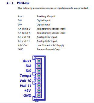
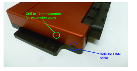
Hello Is the CAN PCB connector and accessability to the board through the casing for the G4X identical to the G4+ ? Reason I am asking is because, the Photograph of the in the G4X manual is missing as compared to the G4+ manual. Secondly, on the G4X, is the procedure to fit an XS expansion loom, and expansion loom part number, identical to the G4+ ? The pinout seems different between them: Here G4+, 8 pin connector: Here G4X, 7 pin connector: TIA for the suport. Dom


-
Hi Adam at the moment , spark edge is set to falling and all seems to work as intended. But I want to be 100% sure It is a 6AL or 6A sorry for my delayed reply
-
MSD igntion boxes, which ones need Spark Edge falling / rising ? TIA
-
Hello I am getting random engine speed spikes. The trigger wheel is the Link 24 teeth and the sensor is also from link. I have taken all precautions when wiring to have a reasonable distance between the high tension ignition wires and the ECU loom. I have attached the log. Can you help ? ATOM2 MSD CDI ignition Lotus Cortina, Distributor synch Atom-DBA-Lotus-Cortina-Random-RPM-Spikes.llg

-
Stevie It is a 4 cyl Cosworth engine in a 70's Formula2 car. Thank all of you for your comments.
-
The TWL_2 is too wide in diameter. I will have to go with the 24 tooth wheel. Do you advise to remove one tooth to get a 24-1 or run with the full 24 teeth and why (I assume) the 24-1 is better than full 24? Great support here. Thank you indeed!

-
Hello Adam Thank you for your comprehensive answer. It just ocurred to me that LINK also sells the disks and a reluctor sensor. Do I assume correctly that the sensor shown at http://dealers.linkecu.com/CAS_3 will work fine with the trigger wheel here: http://dealers.linkecu.com/TWL_2 ? Best regards
-
Hello I need to fabricate / install a custom trigger disk on a inline 4 engine, naturally aspirated. The ECU is a Atom II. What trigger pattern gives best resolution and is easiest for the ECU to work with. Numbers of teeth and missing ones? Sync will be used from the existing ignition distributor. Is it better to use a Hall sensor or a inductive reluctor type sensor ? Thank you for your advice
-
Hello I am facing the problem that Lambda is going considerably rich over time (15 min) in idle despite IAT actually going colder. Injector pulsewidth remains the same and so does load, the cursor remains in the same cell. Do you have an idea how to tackle this? Thank you in advance Dom

-
Hi Adam thank you for the pointer. That must be it.
-
Hello I have logged internally two cars and both logs show the load crosshair on the fuel table at zero kpa throughout the entire log. The value in the log graph shows the actual values. See screenshot below. What both files have in common is that the log is rather long, 70 minutes and 50 minutes.

-
Hey guys ..!!! Thank you so much for the AWESOME support. You ROCK :-) Best regards Dom
-
Hello I want to protect the engine in a low Oil Pressure situation. The signal from the oil pressure sensor (hall) is AN Volt 1 Could you please elaborate how I would configure a 100% ignition cut if the AN Volt 1 value is less than a certain threshold (ie. 0.7 volt) ? At the same time triggering a bright warning LED / light would also be needed. Thank you for your support
-
thank you
-
Hi Adam, Yes, if I have heater current I can determine the approximate temperature. Can G4+ display the heater current form the O2 CAN module ?
-
Hello Is it possible to display the exhaust gas temperature by the means of oxygen sensor heater current (Link CAN O2) in G4+ ? OEM ecu's nowadays often provide this function. Please advise, thank you.
-
Hello Adam, Thank you for giving it thought. Maybe there is a solution still... let's see TIA
-
Hello Dave Thank you so much for your support which was very helpful indeed. I understand the principle now much better. I have the supercharger armed (AND DISABLED) with DI9 input, The clutch operates ABOVE 1500RPM or 25% Throttle pos :-) Now as a last question, would it be possible to prohibit DI9 input (activation of supercharger) if the switch was in the off position and accidentally switched ON above 5000 rpm? The purpose is safety related. If the supercharger kicks in above 5000 when the driver is not really prepared for it to happen, it could cause the car lose traction ..especially in the wet and or in a curve. What do you think ?


