


Pete_89t2
-
Posts
177 -
Joined
-
Last visited
-
Days Won
4
Content Type
Profiles
Forums
Events
Gallery
Blogs
Everything posted by Pete_89t2
-
Well after spending a big chunk of the weekend troubleshooting my wiring harness, and finding no failures there, I'm now thinking something must be broken in the G4+ ECU. Here's what I've done to troubleshoot so far: 1 With ECU disconnected from the loom, I did end-to-end continuity tests of every wire/circuit in the harness, paying special attention to the CAS triggers and coil wiring since it's a no-spark issue. No opens or questionable connections were found anywhere. 2. Since the ECU had to be removed, and the harness partially extracted from where it runs from the kick panel to the fire wall to give me access, I double checked to ensure that none of the harness was being mechanically strained when installed and connected to the ECU. The G4+ ECU is mounted on a fabricated bracket, in the same location Mazda used for its OEM ECU on a US market FD - behind the right/passenger side kick panel, and harness is routed through the same firewall hole, though I used a mil-spec bulkhead connector there, which was included in the continuity testing (#1). 3. At this point failing to find any faults with my wiring, I reconnected the ECU to the harness, but just left it laying on the floor - figured I'd re-do the trigger scope trace tests and the coil tests before putting everything back together. 4. Pulled my fuel pump fuse so the car wouldn't start/flood and took a trigger scope trace while cranking - looked pretty normal, see here: https://drive.google.com/file/d/1SAGkC-o202Dg4A2ZmT0wNdPthUcpF6OQ/view?usp=sharing 5. Also re-ran the coil functional tests, and all 4x coils fired as they should. 6. At this point, I was feeling confident so I decided to remount the ECU to its bracket, and tuck the wiring back in its normal place behind the kick panel, pop the fuel pump fuse back in and take it for a test drive. 7. I had PCLink connected to do a trigger scope trace while cranking, and the car failed to start. Again due to no spark, though I'm seeing normal cranking RPMs displayed on PCLink, but the trigger scope trace is just showing what looks like random noise again. Here's that trace: https://drive.google.com/file/d/1kUutrS31sGNEtz4FGdXTQO7hlVj19KS-/view?usp=sharing At this point I'm stumped as to what to try next - can't think of anything else to check with the wiring that might be a factor. Any ideas?
-
Another update - I take back what I said about seeing zero RPMs while cranking and doing the trigger scope capture. Did the test over, and it turns out the G4+ was reading a pretty normal cranking RPM (250~280 RPMs) while I was taking the trigger scope trace. Trigger scope trace looks the same as what I posted before though, so not sure if I'm using the software correctly and getting a good capture.
-
^That's highly likely, given the pin-out arrangement on the 2 Link connectors and how I organized the grounds on the harness. Both the trigger/CAS inputs and the TTL triggers for coils 1 - 4 reside on the "A" connector, so there is likely a common failure point.
-
Yup, zero RPMs is what I'm seeing while cranking, so I'm going to test the CAS wiring. If the wiring is all good, and I have good CAS sensors, I should see a resistance of between 950~1200 ohms between each trigger pin and trigger ground pin on the "A" connector with it disconnected from the G4+. But I'm still not understanding why when I put each coil output into test mode, they all failed to fire? Does the coil output test do more than just test the output side of the ignition circuits (i.e., just from TTL coil trigger to spark output), or does it also look for good continuity on the VR trigger circuits as well? If it's the latter, then it would explain what I'm seeing.
-
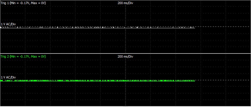
Here's an update - results of trigger scope. Looks like I have a wiring issue to wring out, both of the CAS sensors just show some noise while cranking, see capture.
-
So my FD has been running well with a G4+ Fury for quite some time now, and yesterday I had a sudden no-spark issue after the car was idling for a few minutes. Started pulling out of the driveway and it died before reaching the street. I have solid compression and fuel, so suspecting spark, I hooked up my inductive timing light and cranked - no flashes on any of the plug wires. Plugs & wires are new, so I should have been seeing regular flashes while cranking. Since I had the laptop already hooked up for logging w/PCLink, I decided to put each coil into test mode to see if they fire, again using the timing light. I've done this before with the timing light, so I know it will reliably flash when the coil is in test mode and firing. No flashes on any coil was the result. Next I unplugged all the coils (IGN-1A smart coils) from the harness, and tested for +12VDC at the each coil's power terminals with ignition switched on - all had good +12VDC power. Also tested continuity of the coil grounds, to battery, rotor housing and sensor ground and they all look good; basically 0 ohms on all ground paths. Was getting dark, so I pushed the car back in the garage for the night and will work at it today. Have a couple of questions on my troubleshooting strategy for this: 1. I figure the next thing I should do is take a trigger scope log while cranking to verify that both crank angle sensors are sending good signals to the G4+. I've done this test after initially wiring the car, so I have a baseline of what "normal" looks like there. Obviously a wiring failure or bad CAS sensor will prevent the coils from firing. 2. I'm assuming if either of the CAS signals tested in #1 are bad, then none of the coils will fire. But I'm a bit confused as to why none of the coils were firing when I put each of them into test mode with PCLink, as I thought that test mode only functionally tests the coil outputs? Unless the Link G4+ also tests for proper continuity with the CAS trigger inputs during this test as well? Thanks in advance!
-
Well I think this problem is solved! Took a few drives yesterday & today and had a look at the data. This was after just changing the "I" gain for the E-throttle as Adam suggested. Bottom line is the TP/target error accumulator doesn't go any higher than 10 now, and most times it stays at zero. In fact the only time it rises above zero is when I use the cruise control - the blip you see in the time plot image below occurred right after I hit the "cancel" switch on the cruise control (cruise was set at approx. 60MPH at the time), and I took over control of the accelerator pedal. I'll get a similar magnitude blip in the data when I set the cruise speed, or hit the resume/accel. button. Thanks again Adam!

-
Ok, so then change the "I" gain in the e-throttle settings from the existing 0.125 to 0.05 and do some testing, and if that doesn't improve things, drop the existing "P" gain from 7 to 6.5 as well. For testing to see if the changes are trending in the correct direction, I was thinking I should drive the car with the cruise control, which seems to be a factor that instigates the instability, and see what the TP/target error accumulator data tells us - lower #'s being better. Sound like a plan?
-
Excellent, thanks for the help Adam! I attached the tune file I was running at the time, looking forward to any PID suggestions you may have. Baseline Tune -v1 (post rewire - AS-IS v4 9-21-2020).pclr
-
Hi Adam, I got lucky today and managed to get the code 73 error to repeat. Here's a link to the ECU log on Google drive with the data you requested: https://drive.google.com/file/d/1fWPveBln3SQHru_cT-2_SkuL0Wa5fRps/view?usp=sharing I recalled that while I was previously testing the cruise control function, the code 73 error would be more likely to occur, so that's what I did to try to instigate the error today - toward the end of the log, I set the cruise control at a set speed, cancelled & resumed cruise, and not long after that the code 73 occured. It was accompanied by a code 75 fault this time too. If the ECU log doesn't provide sufficient data, I was also logging on my laptop at the same time - time index in that log where the code 73 failure occurs is at approximately 17min-40sec in. Here's a link to that much larger file: https://drive.google.com/file/d/13SXDvQd1gO757qOT9WCUTkylXImu4qQq/view?usp=sharing
-
Got it, thanks - I'll set up the ECU logging as described and share a log next time it acts up.
-
Thanks Adam, I hope you're on to something - tweaking the tune sure beats messing with wiring! I created a PCLink log as requested. Car was not running, the 1st few throttle movements were on the slow/gradual side, and as the log progresses they get faster & faster, 0 to 100% and towards the end they were more varied as far as start % and end %, but I moved the throttle as fast as my right foot let me. It's about a minute of data, but apparently too big to attach within the 291Kbyte limit the forum has. So instead I posted it on Google Drive - see if you can get to it from this link: https://drive.google.com/file/d/1Z72aUzf-uk_w4X6EPwEnJFTFBNKLl7xh/view?usp=sharing
-
My Link G4+ Fury is installed on a modified single turbo FD RX7 that is running a GM DBW throttle. I can use some help troubleshooting an intermittent problem where the ECU flags a fault code #73, Aux 9/10 supply voltage. This happens very randomly - I can drive the car for several days and many miles with zero occurrences, then it may happen shortly after start up on the next drive or several miles into it. Usually when it does happen, I can use PCLink to clear the fault code and drive home with no problems, but sometimes that drill takes multiple iterations. Anyway, I've been logging data on every drive as I'm still tuning the car, and confirmed in the logs that when it does happen, my AUX 9/10 voltage does indeed drop to about 1.5V in the span of about 1 second. Based on this, I started looking for any possible open circuits or bad connections in the wiring harness and relays (main ECU power and E-throttle relay) that are associated with supplying power to AUX 9/10 from the hot and ground sides. No problems were found there; static continuity & resistance tests of the harness reveal no issues. Same story for voltage tests of the harness with the ignition keyed on but motor not running - I get a steady battery voltage at the AUX 9/10 power supply pin. I also tried to induce the fault with the car idling in the driveway by trying to tap on the relays, and wiggle/tug wires associated with the AUX 9/10 power circuit, but was unable to replicate the failure. The relays I'm using are pretty standard Bosch automotive 5 pin relays, rated at 30A for the NO contacts. The coils on them are not polarized; not sure if they have any diode protective circuitry that some relays have on their coils though. Any ideas on what to try next, or anything I'm missing? I was thinking of just replacing the relays to see if that changes anything. Thanks in advance!
-
^Unless you meant to say "less than" in the statement above. that transient filter would explain why you're not getting many cells filled, not your driving technique. Here's a screenshot of the settings I've been using on my G4+ mixture map, so far it's been working pretty good. Some explanation of my settings - with caveat that I'm a newbie at this too, I'm sure the Link gurus will chime in with possibly better suggestions for us - On minimum samples, I have 10 in there initially, but to get a better result you really should have more samples. Of course doing so populates fewer cells given the same data log - For "Active Zone" I've been using 50%; going smaller gets less samples and going larger gets you more samples. Not 100% sure what the trade-off is though; my understanding is that a smaller active zone % gets you closer to the center of the cell thus the accuracy of the fuel correction calculated is better? - On the conditional filters, I set ECT (coolant temp) to be greater than 180*F, which ensures it ignores any data samples until my engine is at operating temp, and all the warmup enrichment is zeroed out. I also set another conditional filter for Overrun Fuel Cut status <0.5, which ensures that it ignores data collected while the car is in overrun fuel cut (status =1), as it would skew the fuel corrections as well. - For the transient filters, since my car has a DBW throttle, I use AP (accelerator position) <10 units/second. That way it will only use data collected while I had a steady foot on the throttle - you want to avoid abrupt throttle changes and the resulting accel enrichments during the transients

-
I'm using a G4+ Fury on a modified FD RX7 with a GM DBW throttle body, and am trying to set up the Link to implement cruise control. I'm using the FD's OEM vehicle speed sensor on the transmission, which drives both the factory speedo on the dash and Digital Input #1 on the Link as my speed source for driven wheel speed. What I'm lacking is a good number to plug into the "calibration" field for DI#1 - currently it has a 220 there, and the driven wheel speed being logged by the Link with the 220 is way higher than the actual speed indicated on the OEM dash speedo as I drive the car. BTW, I've checked the factory dash speedo against my GPS, and it's pretty accurate - within 1~3% of what GPS is reading. So I'm guessing unless someone knows a specific number I can use for the FD's speed sensor, I'll have to derive it by doing some test drives and logging - drive at constant speed & record it, while simultaneously logging driven wheel speed on the Link. Do this at a few different speeds, and then do the math to figure out the calibration factor. Would this work?
-
That was a quick update - you guys are on point! One other question though - since I'm still in the process of building this car, I haven't road tested the cruise functions yet; all of my testing so far was limited to static powered up testing with the ECU & PCLink connected. After reading thru the revised documentation notes above, and based on how it's formatted as a list, it would imply that the all analog or all digital input note applies to the brake switch, clutch switch and the speed source, as well as the Cruise On/Enable, and Set/Resume/Cancel switch functions. I hope that's not the case, because I have the brake, clutch and speed sensor wired to digital inputs. Anyway, if I'm correct, more clarification of the documentation may be needed here.
-
Thanks for helping me sort this out -- it now works after making a few wiring revisions to the OEM Mazda harness needed to connect the main cruise on/off switch to AN6, so all the cruise function switches are now all on an analog input. Just a suggestion for the next update to the PCLink help file/documentation -- add a note in there to highlight the fact that the cruise function switches (i.e., cruise ON/enable, set, resume & cancel) need to be all on an analog input or all on digital inputs, not a mix of both. Since the documentation doesn't explicitly state anywhere that you can't have both analog & digital inputs for these switches, most guys will design their wiring harnesses around their switch gear and specific installation. In my case, that meant using a mix of an analog & digital inputs to minimize the need to alter the OEM factory wiring.
-
Bummer, I was hoping I wouldn't have to mess with my new wiring harness or the OEM wiring again.
-
I'm not quite following the highlighted statement above. Are you saying you can't use a mix of DI's and analog inputs to implement all of the cruise functions - it's an either/or proposition? I wired it the way I did based on the available Mazda OEM switch gear, and what I had available as DIs/analog inputs. The "cancel" switch is part of the cruise "set/resume/cancel" switch on the steering wheel; it's a 2 terminal momentary contact device that changes its resistance across the 2 terminals depending on which switch is pressed, so I wired that to the analog input along with "set" & "resume". For the cruise on/enable function, I thought I could use a DI for that as Mazda has a separate momentary switch for that on the dash cluster that outputs +12V when it's depressed. I see now that by ignoring the "On switch voltage" threshold under the analog switch thresholds menu, I inadvertently set my "Cancel" and "Cruise ON" to the same values. If I were to adjust the analog threshold voltage for "Cruise ON" to a value that can't possibly happen on that analog input, say 3.5V, based on its design and how its wired, would it then simply accept the on/off input from DI3 as the "cruise on" switch function as I intended it to? If that won't work, then I think your option #1 would make sense, though it won't be as easy since I'd have to de-pin a few terminals in that cruise switch so it doesn't send +12V power to the analog input.
-
Ok, I pulled a couple of manual logs, and attached the tune file. Added a time plot view, and made sure "Cruise control status" is logged/displayed. The file "log #1" is after an ignition switch power cycle; note that the DI3 reverts to latching OFF, and it shows what happens as I press the various cruise control switches individually in sequence - cruise on/enable, then the set/resume/cancel. Also tapped the brake & clutch a few times to ensure those inputs are working. The set/resume/cancel switch is on AN6, and its thresholds are programmed based on the voltages measured in testing and they appear to be set correctly -- but something really weird happens whenever I hit "cancel" - the cruise status changes to "Enabled", then to "Off" when you hit cancel a 2nd time, behaving the way the "Cruise ON/Enable" switch should. The file "log #2" is essentially the same procedure as log #1, except that I set the DI3 latch back to its ON state before recording. I'm stumped at this point, but I also noticed that the lockouts won't allow me to set the minimum cruise lockout speed down to 0 MPH for testing purposes, is it possible that this is what's causing the issues? Log #2 - after reseting DI3 Latch to ON.llg Log #1 - after fresh power cycle (DI3 defaulted to latch OFF).llg Baseline Tune -v1 (post rewire - working copy v2).pclr
-
The car's not running yet, still need to finish fabricating the IC piping, so it will be a while until I can get a log with it running. Would a manually triggered log showing the switch functionality be of any use? It seems to function fine with the settings I have as attached to the 1st post, but for some reason the ECU clears that latch setting on DI3 when the ECU powers down.
-
I have the "Cruise On" switch set to momentary in that menu as well (ref. screen shot in original post), but unless I also set the latching to ON in DI3, the status of the cruise on / DI3 won't remain active when I release the cruise switch. Is this another one of those things where the order at which you apply the settings and save them to the ECU matters? I've also tried changing the "Cruise On" setting you referenced to "toggle", and it behaves the same way - since the hardware is a normally open, momentary contact switch, when I depress it it goes active, and as long as the DI3 latch is set to ON it will stay active until I press the switch again. But regardless of the way I have the "cruise on" set (momentary or toggle), I lose the DI3 latch setting when I power down; on power up, it defaults back to OFF.
-
Some background - I recently finished a rewire of my series 6 FD RX7, which is running on a G4+ Fury. Since it has a working DBW throttle body, I'm trying to restore cruise control functionality using the OEM Mazda switch gear and the G4+. Attached is my current tune file for reference, and a screen shot of the "Cruise" tab view I have set up in PCLink, with all the relevant cruise control settings. The problem I'm having is that "Input latch" setting for DI 3, which is used for the "Cruise On" function that you see above won't persist in the ECU after I key off the ignition switch. Since the Mazda OEM "cruise on" switch is a momentary contact type, which sends +12V power to the DI3 input when pressed, I have the ON level set to HIGH, and I need to use the latch function to keep its state ACTIVE after releasing the switch. After saving these settings to the ECU, I tested them and they appear to work as they should (i.e., DI3 goes ACTIVE when I hit the cruise ON switch, and OFF when I hit it a 2nd time), but I discovered that if I shut the ignition off and then turn it back on, I'll see that the latch setting reverts back to its OFF state. All the other settings above persist as they should after a power down/up cycle. Any thoughts on how to fix this, short of replacing the OEM switch gear with a toggle switch? Baseline Tune -v1 (post rewire - working copy v2).pclr

-
Thanks, I didn't think of using a Zener diode & pull down resistor but that's a neat solution. Though the 4x series diodes should be physically easier to add inline to my wiring harness at this point.
-
Hi, I've got a wired in G4+ Fury in my FD, and I'm attempting to use DI6 as the "A/C Request" function. Long story short, it's not working as expected but I think I know why - voltage on the DI6 input is a bit higher than it should be when the AC is switched on, and that voltage varies depending on AC blower fan speed. Here's the voltages I measured on DI6, car not running but with a trickle charger connected to the battery: A/C switch & Fan Switch OFF: 12.4V A/C switch OFF, Fan switch set at ANY speed: 12.4V A/C switch ON, Fan speed 1: 1.51V A/C switch ON, Fan speed 2: 2.16V A/C switch ON, Fan speed 3: 3.36V A/C switch ON, Fan speed 4: 3.14V What is the recommended work around for this? A relay would work, but would be a bit more difficult to physically wire, so I was thinking a few diodes in series to drop the voltage input to DI6 would be a better/easier solution. Question is what is the voltage threshold for the DI, and how many series diodes would I need to reliably pull the voltage down enough? Thanks!


