


Pete_89t2
-
Posts
177 -
Joined
-
Last visited
-
Days Won
4
Content Type
Profiles
Forums
Events
Gallery
Blogs
Everything posted by Pete_89t2
-
Sure, go to this page: https://www.bankspower.com/series-2-idash-1-8-datamonster-and-supergauge.html?gclid=EAIaIQobChMI1LjKuP-68AIVzv_jBx0NrQJrEAAYASAAEgJfMfD_BwE Then scroll down about 1/2 way down the page, looking for "Supported ECUs", where it lists all the ECUs supported, and each has a link to a .PDF file that lists the parameters for that ECU
-
Thanks Adam, I downloaded the lists of parameters Banks supports for Haltech (pasted below FYI); doesn't seem to be any logic behind the selections of parameters displayable for each ECU. I also downloaded the iDash user manual, which describes how to setup the gauge for use. One of the 1st steps in the procedure is to select the aftermarket ECU, which is where the Link, Haltech, etc. appear in the drop-down list. I'll have to confirm this with Banks, but this implies to me that once I select a Link ECU, the Banks firmware will only let it display parameters from their list for Link ECUs. I did take a look at the Plex uDSM - it does everything I'd ever want and more, though it's a bit more expensive. Only issue I have with the Plex is it's form factor - not many flat surfaces in an FD's interior where I can mount it, still see it driving and not have it look look tacked on or out of place. If Plex made the uDSM in a standard 52mm or 60mm round gauge format, there are lots of options that would work in an FD (i.e., center dash speaker pod; A-pillar pod; steering column pod). FYI, here's the Banks list for Haltech: Throttle Position Accelerator Pedal Pos Boost Control Output Intake Cam Angle Bank #1 Intake Cam Angle Bank #2 Exhaust Cam Angle Bank #1 Exhaust Cam Angle Bank #2 Reserved (Fuel Level) Fuel Temp Fuel Consumption Rate Fuel Composition Fuel Trim Long Term Bank 1 Fuel Trim Long Term Bank 2 Fuel Trim Short Term Bank 1 Fuel Trim Short Term Bank 2 Lambda 1 Lambda 2 Lambda 3 Lambda 4 Injector Duty Cycle (Primary) Average Fuel Economy Boost Control Target Manifold Pressure Barometric Pressure Oil Pressure Fuel Pressure Manifold Pressure 2 Coolant Pressure Brake Pressure RPM Turbo Speed Sensor Wheel Speed Front Left Wheel Speed Front Right Wheel Speed Rear Left Wheel Speed Rear Right Coolant Temp Oil Temp Transmission Oil Temp Air Temp Air Temp Sensor 2 EGT 1 EGT 2 EGT 3 EGT 4 EGT 5 EGT 6 EGT 7 EGT 8 Diff Oil Temp Gear Ignition Angle (Leading) Knock Retard - Bank 1 Launch Control Ign Retard Knock Level Logged Wheel Slip Fuel Cut Percentage Battery Voltage
-
I'm considering one of these Banks gauges for my S6 RX7 that is running a Link G4+ Fury: https://www.bankspower.com/i-2695-banks-idash-supergauge-no-obd-primary-gauge-for-vehicles-without-obd.html#! After researching other CAN bus gauges on the market (GaugeArt, Perfect Tuning, BTI), I kind of like the appearance of the Banks gauge, and the fact that it can legibly display the most parameters on a single screen. After downloading the list of parameters Banks claims to support for the G4+ ECU, I was disappointed to find that a few parameters I'd like to be able to display from my G4+, such as Target lambda/AFR, and Injector DC(Secondary) are not among the list of supported parameters. But it does support a large list of parameters I don't care about; i.e., any cam related stuff because rotary. So I was wondering if there was any flexibility there to program the gauge or the G4+ to substitute the parameters I'd rather monitor. Unfortunately, Banks tech support has been unresponsive to my inquiry thus far. So I was wondering if anyone here using a Banks iDash gauge with their Link G4+ was successfully able to get the gauge to display any parameters from their G4+ CAN bus that are NOT among those listed below from Banks list? If so, what did you have to do to make it happen? Link ECU Parameter name: Fault Codes MAF TPS Cam Inlet Position L Cam Inlet Position R Cam Exhaust Position L Cam Exhaust Position R Injector Timing Lambda 1 Lambda 2 Injector Pulse Width (Actual) Injector DC MGP MAP Barometric Pressure Oil Pressure Fuel Pressure Engine Speed LF Wheel Speed RF Wheel Speed LR Wheel Speed RR Wheel Speed IAT ECT Oil Temp Gear Position Ignition Timing Knock Level 1 ECU Volts Thanks!
-
@Adamw - Curious as to why MGP on both tables is the preferred load axes in this case, as opposed to having MAP on the AFR/Lambda Target table and MGP on the Fuel Table? While my car is very different being a rotary (13B-REW), it shares similar characteristics to this one, namely being turbocharged, with a single throttle plate (GM DBW, 90mm) and a plenum (using the 13B-RE Cosmo upper & lower intake mani). I could be completely wrong, but I thought it was best to use MAP on the AFR/Lambda target table, in order to correct for altitude, and then use MGP on the Fuel table?
-
Please help me understand the relationship between the Charge Temp Approximation table, and the IAT Fuel trim, when operating in the Modeled Fuel Equation mode. According to the help file block diagrams for Modeled Fuel Equation, the Charge Temp Approximation table is one of the required inputs that results in the "Air Charge Estimate" output, which in turn is an input to the Fuel Mass Calculation block, which outputs the "Fuel Mass to Inject". Based on this, is my understanding correct that if I'm using Modeled Fuel Equation mode, and I have a good IAT sensor & measurement, and I input correct data into the Charge Temp Approximation table, I can turn off/zero the IAT Trim Table, and not worry about the impact of changes in IAT/charge temps on lambda/AFR? Is the IAT Fuel Trim function/table just there simply to give the tuner who uses Traditional Fuel mode the option to trim fuel to IATs when he doesn't want to mess with populating a charge temp approx. table? Thanks in advance!
-
Never done this before, but in theory the maximum pressure you should see in normal operation would be the relief pressure specification of the radiator pressure cap you're using. So if the cap is rated at 16psig, that's the max you would see on a gauge. I would think a blown head gasket would increase coolant pressure, but only up to the point where the cap relieves it, so again if the cap is functioning it would be 16psig in this example.
-
When using the PC logging, is it possible to append logs from multiple road tuning sessions to create one very large log file that captures the data from the multiple road tuning sessions? Normally when I record a PC log, and hit save, it saves the log from that session and gives the file a default name with the date/time. Now if I take the car out the next day for another road tuning session, and record log data, if I were to hit "save as" and select the same log file name from the prior day, will the new data be appended to that log file (creating the larger log file I want), or will it overwrite the prior log's data? My goal here is to get lots of road tuning data into a large log file for more productive use of the Mixture map tool. Thanks in advance!
-
Thanks Adam, I think I have a strategy for tuning this table now. Worst case for heat transfer from the engine block to the intake air would be when the air is stagnant or not flowing rapidly thru the manifold, so I think idling or cranking to start after a heat soak would represent a worst case condition. Here's the test I came up with, based on your advice above - please comment if I'm missing something: 1. Set the entire charge temp approximation table to zeros 2. Get car up to full operating temperature and let it idle while logging my CLT, IAT, UIM air temp and lambda (measured & target), with closed loop lambda turned off. Use this data to baseline how well measured lambda tracks with lambda target at idle speed. 3. Use a heat gun to blow hot air over the intercooler core - this should raise the IAT & UIM air temp values fairly quickly. 4. While doing #3, watch the lambda's to see how much the measured lambda deviates from target. 5. If there's minimal to no deviation, I can leave the charge temp table set at all zeros, otherwise start incrementing the charge table cells around idle by a small amount, say 5% each step, while watching lambda's to try to null out the deviation to close to zero.
-
I'm using the modeled fueling method on my G4+ Fury, and am looking for guidance on how to properly set up this table. I understand the math behind how this table is used to compute a charge temp from the IAT and CLT inputs, but was interested if anyone had some empirical data for the FD to share to inform these table inputs. In my case, I have a fast reacting GM IAT sensor installed in the throttle body elbow, and I also log data from a 2nd Bosch air temp sensor that is installed in the OEM location in the upper intake manifold (UIM). Generally, these 2 sensors track and agree with one another to within a couple of degrees F, but after heat soak condition (e.g., shut the car off hot & restart ~ 10 minutes later), the sensor in the UIM will initially read about 10~20*F higher than the IAT sensor in the TB elbow, and after a few minutes of driving both sensors temp readings will drop, and they will match temps again within a few *F. Given the above observations, I'm thinking my charge temp approximation table should be populated with zeros for all RPMs and MAP values at idle or above, and perhaps no more than 10~15% at MAP values below idle for all RPMs. My rationale here is since the intake path from the TB elbow to the engine's intake port is relatively short, the air charge won't receive much heating beyond its measured IAT value at the TB or UIM. Thanks!
-
Adam is spot on with the battery; I can also see in that log that your alternator isn't putting out enough juice to charge the battery (i.e., >13.5V) until your RPMs get above ~ 1500RPMs, so there may be an alternator issue as well to deal with. Recommend putting in a new battery, and then test your charging voltage at idle.
-
Probably a dumb question, but assuming I make the tweaks as described in that Realdash.pdf document previously posted to connect the Realdash app on my android smartphone via the USB tuning cable on my Link Fury G4+, would those changes prevent or impede me from using PCLink tuning software with a laptop? Obviously not looking to run both apps off the same USB cable simultaneously; I just want to know if I would need to revert the tweaks required for connecting the Realdash/smartphone usage before plugging in the laptop again and using the PCLink app? Thanks!
-
Thanks, ^that would explain it. Just checked, and the "Run when stalled" was set to YES. A few weeks ago I flipped that setting from NO so I could tune the post-start & warm up enrichment tables for the cold weather, and forgot to flip it back when I was done. Looks like the sensor is toast though, I tried running it again with that setting flipped OFF, and am still getting the errors in the log and the 0.000 average lambda readings.
-
I'm running a G4+ Fury with the internal lambda sensor. Normally, shortly after starting the car and the sensor reaches operating temperature, I'll see average Lambda values on PCLink display reasonably close to the target lambda value. Today the average lambda was staying at 0.000, and it didn't budge, so I pulled a log to try to figure out what was going on. Not sure what to make of the data in the log, but it looks like some weird behavior based on the "Lambda 1 Error" status messages in the log. If someone can take a quick look at the log file linked here and advise, I'd appreciate it: https://drive.google.com/file/d/1wodWGzd4PBJP7jFdQRx6a4WuSzwUoUbm/view?usp=sharing And here's the current tune file I was running at the time: https://drive.google.com/file/d/1jPCsRCLMRtozSdaqYYVm13LsM8ChNkR1/view?usp=sharing Ideally the log will conclusively tell me the sensor failed and rule out any potential wiring issues. But since this sensor was working fine for quite some time now, and I haven't messed with its wiring recently, my guess would be the sensor simply failed. Thanks!
-
I'm running a G4+ Fury with a modified single turbo FD RX7. Since I added a couple of Bosch knock sensors to the motor (1 on each rotor housing in the OEM location, using the Bosch broadband "donut" style sensors), I was wondering how I would go about testing/characterizing the sensor's outputs, but not necessarily have them do anything with regards to actually control knock at this point? (i.e., take action to retard timing, etc.). Will setting all the values in the Knock Target Table to maximum of 1000 do the trick? That way I can log the outputs of my knock sensors without them intervening with anything? Thanks!
-
Thanks gents, it seems I did forget to hit "enter" after making the changes yesterday - re-did the procedure and all is good now! Surprised my motor was running as well as it was, as the trigger cal done by the previous owner was about 8~10* more advanced than it should have been.
-
Hmmm, I'm pretty sure I did, but I'll try the procedure again later when I'm back to the garage and let you know how it goes
-
Some background - I've got a series 6 RX7 that is running a G4+ Fury, and its using the OEM VR trigger wheel & VR sensors. The car's previous owner originally did the trigger calibration procedure, but I'd like to be able to verify it to ensure it's correct, so I set out to follow the rotary trigger calibration procedure as described in the help file. Following that procedure, after I hit "Set Base Timing" in the calibrate menu, the set base timing window opened up as it should and I can change both the "Lock Ignition Timing" and "Adjust Offset" values, but any change made here appears to do nothing to the actual timing when cranking & verifying with a timing light - it appears my base timing doesn't change even when I change these settings in the "Set Base Timing" menu. Appears these settings are locked somehow, how would I go about unlocking them? Thanks!
-
I've been using a program called TinyCAD for my schematics. It's a freeware program, runs on Windows, and is pretty easy to figure out and use. It also includes a pretty decent library of electrical/electronic components (resistors, diodes, etc.), and you can create your own components to add to the library. More info & download can be found here: https://www.tinycad.net
-
Some background - I recently got my G4+ back from Link after they serviced the ignition drivers/header connector. Reference this thread: https://forums.linkecu.com/topic/12884-troubleshooting-a-sudden-no-spark-issue-fd-rx7/ Upon getting my ECU back a few weeks ago, I had no problems loading my existing/unchanged calibration file onto the ECU, running a few pre-start tests (coils, injectors, etc.) and firing up the engine. Ambient temps were significantly warmer then, ~70*F vs 40*F now. Anyway, the car fired right up fine, and ran fine - I let it reach operating temperature, had it running perhaps 30 minutes or so until moving it onto my lift where its been parked to do some other work underneath it in the two weeks since. I'm now having a problem now where the engine floods profusely when I attempt to start it - I know it's flooding because when it does, fuel will leak past the metal exhaust manifold gasket leaving a mess to clean up. Tested spark & compression, and both are good. Today after tweaking the cold start enrichment functions to lean things out a bit, and cleaning the mess from the fuel, I got the car to fire up and run for a few minutes, but as the ECT temps approached ~90F, it died again. I tried restarting a few times, and it would catch and run briefly and then flood out again, as evidenced by the fuel leaking past the exhaust mani again. Not really sure if this is a tuning issue, or perhaps leaky/malfunctioning injectors at this point, so I was hoping someone could take a look at my tune file & log and provide some advice. Here's the link to the tune file: https://drive.google.com/file/d/1nQZskfVPU3lOYqef57xHLf_m92gXHt8L/view?usp=sharing And the Log file: https://drive.google.com/file/d/1yWCB5PIgKToOYSq11qcuOrcIFD1gl8_Q/view?usp=sharing As far as the injectors leaking, I tested for that by pressurizing the fuel system (engine not running), and letting it stay pressurized at the 43.5psi base pressure for about 20~30 minutes. There were no external leaks found, so if any of the injectors were leaking or sticking open, fuel would find its way into the combustion chamber and/or leak from the exhaust manifold gasket. No fuel was noted after pulling the plugs or leaking past the exhaust mani gasket, so it seems the injectors are OK? Thanks in advance!
-
Just an update to let you all know how this turned out... First off all, I am very grateful for and impressed with the excellent customer service I received from the folks at Link NZ and Link USA - they really do stand behind their product! Nice to see that, especially when compared to experiences I've had with competing ECU makers that seem to excel in making excuses for NOT helping out a customer when things go wrong. Anyway, I decided to ship my G4+ Fury to the Link USA office for a look since I could find nothing wrong with my wiring. The tech there put it thru a set of functional tests, but could not replicate the problem I had where the coils would intermittently not fire. However, upon visual inspection of the circuit board, the tech noted potential cold solder joints where the A & B header is soldered to the circuit board, so my ECU was then shipped to the Link NZ headquarters for a more detailed inspection & testing. The Link NZ tech couldn't replicate the problem either, but nonetheless decided to replace the coil driver circuitry and replace/re-solder the A & B headers before shipping it back to me, along with some new terminals for the A & B looms, so I could re-do those coil pins if necessary. I opted not to mess with my wiring and plugged in the serviced G4+ as it was received, and ran thru all the appropriate per-start up functional tests with PC Link - triggers looked good on the trigger scope, and all coils passed functional testing without issue. Car fired right up and ran well! Though now that it is significantly colder here, I'm finding that it wants to flood when trying to start cold - need to tune the cold start enrichment properly, which hasn't been done yet.
-
I'm really liking the new default layouts that come with the current version of PC Link, but is there an easy way to somehow merge or combine pages/tabs from an existing layout into the new default layouts? As an example of what I'm trying to do, since I'm working on a Mazda rotary, I have no use for the default VVT page, so I'd like to replace that particular page with an OMP (Oil Metering Pump) page that I created in my existing layout. Thanks!
-
It certainly is an odd one. My best guess is that the ignition drivers/circuitry is fine, but there may be a defect in the "A" header itself causing an intermittent connectivity failure - perhaps a cold solder joint where the header pins connect to the circuit board? This might explain why moving the ECU around and removing & reinserting the connector had some impact on the behavior. I'd probably opt to send it to the NZ HQ for testing, unless you guys tell me you're confident that the USA support office has the capability to thoroughly inspect it for soldering or circuit board defects. That's good to know, might improve my odds of finding an ECU to substitute locally.
-
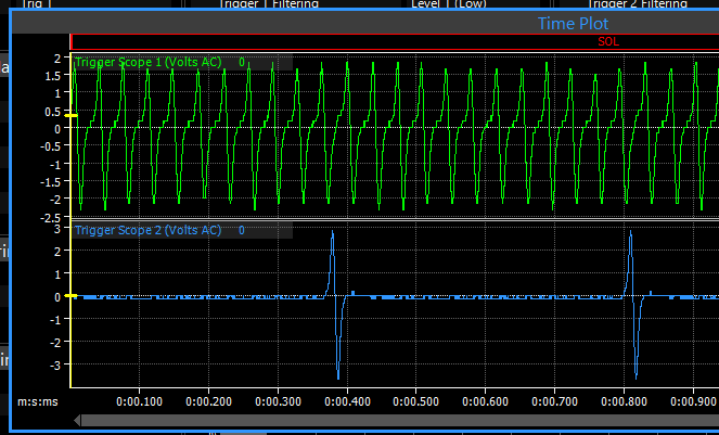
Of course, why do you ask? Below is a partial screen shot of the trigger scope trace from repeat test #1. I'd post the logs here, but they were too big to attach, so I linked them on a Google share.
-
Ok, I repeated the tests again, this time using the trigger scope capture correctly. Results as follows: #1 - Repeated test with G4+ secured in its bracket, fuel pump fuse removed so car won't start/flood - CAS triggers look pretty good to me, see linked log trace here: https://drive.google.com/file/d/1nGLm1EYB0MYAOXjyY8gtjrYhJA30_UWV/view?usp=sharing Next I ran the functional test for the 4 coils again; this time around coil output #2 and 4 were firing consistently, but #1 was intermittent (started dead, then started firing), and #3 was dead the whole time. Instead of relying on the inductive timing light, I tested each with a removed spark plug that was grounded to the engine block with a jumper cable, and watched for the spark #2 - Repeated test with G4+ laying loose on the floor, fuel pump fuse removed so car won't start/flood - CAS triggers looked good again, see linked log trace here: https://drive.google.com/file/d/1ZdyS_rkaZ0iyiTlru4gTMOkipJMev2yE/view?usp=sharing Repeated the coil test, with similar results to #1 - only difference was coil #1 was firing consistently this time, #3 was still dead. Given the coil test results, I unplugged the "A" & "B" connectors from the G4+, and repeated my continuity tests of all the coil wiring. Once again, all the wires had solid continuity from the appropriate "A" connector pin they originate from to the corresponding coil plug termination. I also removed my coils from the FD and plugged them into my FC (uses same IGN 1A coils with an AEM Infinity ECU), just to verify the coils were good, and the FC fired right up and ran on them. At this point I'm 100% certain there is nothing wrong with my harness wiring, or the coils, and that I may need to ship the ECU in for service as my last course of action. Wish I knew someone local with a spare Link G4+ Fury that I could use for testing. Anything else I might be missing here before shipping it in for service?
-
Yes, that's correct - only difference was the removed fuel pump fuse and the ECU & loom laying slack on the floor rather than being mounted and tucked under the kick panel where it would normally be. Haven't had a chance to repeat the successful test, will get to that tomorrow. I'm only clicking capture once, but perhaps I'm doing it wrong - I've been hitting the capture button just prior to turning the key and cranking the motor, so I expected the trace to show just noise for the 1st second or two before the cranking starts. Should I wait until the engine is cranking to hit capture instead? Here's a link to the current tune: https://drive.google.com/file/d/12BwupTZMtN24X3NW4YClSEx1AApt6Y2I/view?usp=sharing One other change I made that applies to both the successful & unsuccessful tests was that I installed the latest G4+ firmware that was recently posted.

