


Mike928
-
Posts
114 -
Joined
-
Last visited
Content Type
Profiles
Forums
Events
Gallery
Blogs
Posts posted by Mike928
-
-
Well Adam, I'd love to "Set up like my picture" but I'm obviously doing something wrong.
I've got 'Trigger Setup' and 'Trigger 1' exactly the same but 'Trigger 2' I only have the option for 'Cam Type" Off or 4 different camshaft selections?
I'm looking in 'Configuration', 'ECU Settings'? I don't have the G4+ Thunder connected.
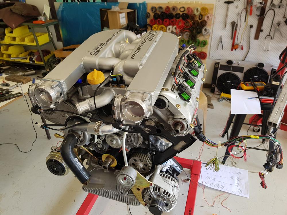
[My motor is a V8 4 cams with the hall sensor on the rh exhaust cam and a reluctor on the crankshaft 60-2]
-
17 hours ago, Adamw said:
Most likely set like this:

Thanks Adam but my 'Trigger 2' is fir VVT? and I can't see how to change it. Under VVT I have selected 'Off' but it is still there as trigger 2?
-
Working my way through the PCLink setup, What 'Trigger' parameters should I have?
It is default to Ford BA XR6?
My engine uses Hall sensor on the rh exhaust cam and a reluctance type crank sensor, 60 minus 2 I think??
-
ok, only one last issue to resolve and I'm all wired up, engine at least.
I set the Thunder software to be DI 6, cruise on. DI 7, cruise cancel/off. DI 8 cruise resume.
I then went to the cruise stalk with my multi-meter to see which wires did what and here's what I found;
Black was 12v input, so I planned for it to be earthed, so Link can switch low. So working from this point I checked for continuity with the other 3 wires.
In the rest state, Black and Brown are 'common' or connected, this becomes open circuit when the lever is moved to 'Cancel'.
Connection is made with Blue when the lever is moved to 'Reset'.
Connection is made with Yellow when the lever is moved to 'Set/Accel.
My question is, Can I use this cruise stalk with my Link Thunder? if so how should it be wired?
Maybe, Black=Ground, Blue=Reset/Resume, Yellow=Set/Accelerate and forget Brown?
-
16 hours ago, Adamw said:
As I mentioned above, pin 5 is connected to the calibration resistor that is in the back of the connector, it doesn't have a wire to the sensor.
Oh, finally I think I get it!!!
Even though there is no green wire on the Bosch plug to the O2 unit, I must never-the-less still run a green wire from the loom plug back to the ECU. This will then connect to the resistor in the plug.
The grey wire, I run to 12 volt ignition power source.
Thanks for your patience Adam! For the life I couldn't see why one would connect a wire to an empty pin socket.
-
16 hours ago, Adamw said:
Note from the help file below.
Pin 4 is the +12V power supply, it needs to come from an ignition switched source.
Pin 5 is the calibration resistor (inside the connector), it needs to be connected to the Thunder MES pin. The "green" is a bit misleading - there is no wire on the sensor side of the connector. Green is just Bosch's convention for that pin back to the controller.

Thanks Adam.
How does the Thunder ECU get the MES signal when my LSU 4.9 O2 sensor has no pin 5 wire? Bosch have that hole in the plug blanked off!
-
I have assigned DI 6 to cruise on, DI 7 to cruise off and DI 8 to cruise resume??
My next dilemma is the Bosch LSU 4.9 O2 sensors. In my Link G4+ Thunder Gick Start Guide it lists the following;
MES sensor green pin 5
RE sensor black pin 6
Heater sensor white pin 3
IPE sensor yellow pin 2
APE sensor red pin 1
ie no pin 4 grey?
On my actual O2 sensor Bosch part #0 258 017 025, I have no green wire to pin 5? the plug blanks out this pin? but I downloaded the spec sheet from Bosch for this exact part # and it lists all 6 wires.
Any advice would gratefully received.
-
On 10/23/2020 at 8:51 AM, Adamw said:
Yes.
Basically in your car the "ON" switch and the "Cancel" switch are the same thing (backwards on the stalk). Some cars have seperate On and cancel switches - so you can cancel and resume without having to set the speed every time.
I'm not sure this correct Adam? Please have a look at the attached page from the owner's manual. It shows 3 separate positions.
Currently, I only have An Volt 9 on B24 [white/green] assigned to cruise function and Aux 8 on A26 [orange/purple] assigned to cruise light.
I'm guessing [scary] that I need more?
The wiring is progressing, see photo and thanks heaps.

-
Hi Adam,
Can you tell me if, On the cruise, does 'yellow is set DI' mean connect it to a digital input? Thus another DI for each of the others?
So Link just cancels via brake input?
-
15 hours ago, Adamw said:
Ok, all looks fine to me.
For the cruise switch; Black can be gnd or 12V. Yellow is Set DI. Brown/Blk is Cancel or On DI (Link needs On sw as a minimum, but doesnt need cancel). Blue is Repeat/Resume DI.
I think I will actually power the SSR from the PDM on a 7.5 amp point with a 10 amp wire and loop the next door 7.5 amp in to feed it 15 amps. There are plenty of 7.5 amp points.
On the cruise, does 'yellow is set DI' mean connect it to a digital input? Thus another DI for each of the others?
So Link just cancels via brake input?
-
On 10/13/2020 at 9:08 AM, Mike928 said:
OK Adam, I can do that. I can supply their voltage from an ignition source through 2 solid state relays? Or can one relay feed thhe both? 10 amp should cover them should it not?
The cruise switch schematic is as I've drawn it. I copied it from the factory diagram. It has 4 wires black one is from the ignition and the other 3 go to the control module. Control module wires go to constant 12v, speedo, earth and bulb check unit and 2 to the actuator, which is vacuum controlled on this model and aren't very good.
The column stalk has 3 operation positions; forward = set/accelerate, down = resume, backward = cancel
Here are my mods. I've run a fresh supply for the E-throttles as the PDM has few outputs over 7.5 amp.
Also the schematic for the cruise switch.
-
14 hours ago, Adamw said:
Pins B5 and D1 are the DBW supplies, ideally they would come from their own relay/PDM output that the ECU can shut off in the event of a safety concern. See the diagram in the help file page: Wiring Information > Output Wiring > E-Throttle > Generic Internal E-Throttle Wiring for more info.
For the cruise switch, do you have a "schematic" type diagram of it? How many buttons/switches does it have and how many wires?
The VDO settings in the help file usually work ok with most Bosch throttles.
OK Adam, I can do that. I can supply their voltage from an ignition source through 2 solid state relays? Or can one relay feed thhe both? 10 amp should cover them should it not?
The cruise switch schematic is as I've drawn it. I copied it from the factory diagram. It has 4 wires black one is from the ignition and the other 3 go to the control module. Control module wires go to constant 12v, speedo, earth and bulb check unit and 2 to the actuator, which is vacuum controlled on this model and aren't very good.
The column stalk has 3 operation positions; forward = set/accelerate, down = resume, backward = cancel
-
16 minutes ago, Gsab said:
Mike, did you ever find PID settings for the 82mm Bosch t/b ?
I haven't looked for 82mm but the supplier [efi solutions] of my 74mm bodies supplied the pinout for them.
Interestingly, I have 2 Mercedes/Bosch bodies, 74mm that are close to identical to the new ones I bought but the pinout seems different, in that when I power plate, it works backwards!
-
I've been finalizing my E-throttle setup and I'm about to wire it up.
There have been a few changes to correct some stuff, so I'd be very grateful if this attached drawing could be checked, I really need to get this right.
Also, the cruise control switch on the bottom left of the drawing, is the stock Porsche one and is part of the column stork but the factory wiring diagram show all but the power feed wires just going into the control module.
Is there any way to work out what I should hook to my Thunder EU and where?
-
I found this video on youtube, 'very basic' instruction but clear. It seems I've gone way too far into the plug and I didn't need to separate the halves.
2 minutes ago, 928sg said:about 2 minutes and 25 seconds into this video
Thank Sterling, you found the exact same one, well done.
I've been over thinking it!
-
I'm not getting your file Adam. It downloads as IMG_2393.MOV and previews as finger and thumb holding the plug but fails to do anything else.
I had a look at plugs B & C to see the structure and I want to remove 10 of the wires from plugs A & B that I wont be using and put them in C or D.
I've got the role of the white lock bit and can see that it frees the pins but when I try to open up plug A, the pins don't want to come away from the white bit.
I've slid the large black bit back down the loom a bit, to give me room to work and some wires/pins will move as if they want to come out but others are pulling on the whit lock piece and I don't want to bust anything.
-
Is there a method, tools or a description of the assembly and disassembly of the AMP loom plugs, A, B, C &D?
I'm quite familiar with Deutsch type plugs but these are quite different.
-
1 hour ago, Adamw said:
Ok, I had a quick look. Assuming you have 2 times E-throttles? Im not sure if you have any of the below connected to the C & D plugs but I will mention them anyway:
You will need 2 extra aux outputs assigned as E-throttle relay 1 & 2.
Your 4 TPS sensors will need 5V and gnds.
You will need a gnd out to the AP sensor.
Fuel pressure needs a gnd out.
Oil pressure needs a 5V and a gnd out.
You've got no aux assigned as Fan.
yes 2 x e-throttles
Well spotted on the fuel pressure/temp sensor ground. I have it in the drawing and on my spread sheet but missed it out of this!
Plug D Pin #1 will have power from the front Power Distribution Module for Aux 17 & Aux 18
APPS is grounded @ Plug D Pin #5
Oil Pressure is powered from Plug A Pin #32 +5V and grounded @ Plug B Pin #22
My fans, 4 of them are controlled by dedicated controllers
i didn't omit pin outs for plugs C&D, I've only just finished them.
I'm most concerned about getting the E-throttle/pedal correct and I keep reading.
thanks heaps Adam.
-
OK, here's what I hope is my final layout, subject to your advice, for plugs A & B.
-
I've just opened my Loom A & B packets and I find some of the wires on Loom A are labelled. Nice.
What is the intended purpose for Green wire from Gnd Out [pin A24] marked TPS 1?
Throttle position sensor as in mechanical throttle body, or TPS 1 in E-Throttle [if so, which throttle body], or throttle pedal position sensor?
I thought I had my 2 E-Throttle wires all sorted until I found this.
-
So, is it best to solder straight into the 'D' plus and forget the connector?
-
I have 2 Link Thermo-couples to connect to my Link Thunder and they come with substantial heat resistant shielding.
What is the recommended method of connecting them to the 'D' plug on the Thunder, for future service?
Connecting then directly into plug 'D' would mean changing them [if one ever failed or got damaged] would be a hassle.
Can I simply put a Deutsche 2 pin plug at or near the Thunder ECU?
-
I think I'll use the 6mm holes that the stock throttle body mounted to, as I'll have nothing in the valley except the 2 knock sensors.
Plus there are the original earth points [MP IX & MP VIII] on the bell housing.
I have also increased the size of the earth cable from the chassis rail to the lower block and the 2 from the inner guards to the 2 cam towers [MP III & MP X].
-
My question goes back to the Porsche Cayenne Coil-On-Plugs by Beru.
Having read a document by Beru on the development of these 'pencil' type coils, it's clear that they use a primary current of 15 Amps.
I've attached a pic of a coil connector to show the size of the wires used. The red/yellow wire #3 is 12v constant and the first brown wire is ECU Gnd and the smaller brown wire #2 is the engine Gnd.
The Link Thunder does not have ECU Gnd wires anything like this size, so, will this be an issue?


Thunder PCLink settings
in G4+
Posted
Got it!
What I was missing was the second level in the tree under Trigger 2?
20 years as a computer tech and get tripped over by a folder tree!