


Ducie54
-
Posts
488 -
Joined
-
Last visited
-
Days Won
33
Content Type
Profiles
Forums
Events
Gallery
Blogs
Posts posted by Ducie54
-
-
If this is the correct wiring Diagram try wiring it like this.

-
-
-
Is it possible to have a Cal table for Digital input frequency. That way we could we could convert a frequency to say a flow rate.
-
-
I'm not going to argue the mechanicals and theory behind the surge tank. The OP was asking about wiring up soild state relays . No wonder why he went to another forum to find an answer. I tried to answer his question you did not, that is not a assumption.
-
I think your over complicating things. Put it on a dyno, do a run with it off and a run with it on. Where the power lines cross is your switch point.
-
The return line from the surge tank is at the top not the bottom so i cant return to the fuel tank. Not to mention most fuel pumps have a internal check valve
This is the way i've setup mine using PWM lift pump.

-
Pin 85 should be connected to ground
-
Thanks Adam ill give that a try.
Yes the math is simple but why have a data log that does not show the true results. Fuel flow on the return v DC of the pump at different pressure would look out and is not what i wanted.
-
Hi Adam
How does that take into account the multiplier and Max DC clamp in fuel pump control open loop?
Is it possible to keep fp speed active? Or do I need a signal generator?
-
Im using a NZEFI PWM fuel pump controller and i'm trying to measure fuel flow return at different DC% I figure i cant use a GP PWM table due to the required multiplier and DC% clamp.
How do i go about keeping AUX 4 FP speed active when the car is not running?

-
I have no issues either
-
From my understanding your fuel pressure log shows that pressure drops with boost. Also at idle your fuel pressure is 33.1 plus MGP of -6.7 gives base pressure of 39.8
It looks like your using a NZEFI PWM controller your DC are to low causing the pressure drop. I would set it to 100% until you have things sorted


Is there any reason why you using a 3D dead time table? This is the data from there website

-
What injectors are you using? The dead time table is a little different. It looks like you entered PSI numbers instead of KPA
How did you set your base fuel pressure? as i read the logs as 39.7psi
Your knock Target table is set to 0 and active. Its pulling timing out
Yeah Dave
")
-
How have you wired it in? I didn't think u needed the resistor.
Is the ground wire large enough? Is it grounded to the chassis or battery?
-
I would be asking Simon as to why there soldered and not crimped. Crimping tools are not that expensive, the cheap ones worked will on my harnesses.
I can't understand why the power wire has the shield attached to the pin. If it's grounded in the CAN lambda module that will give you issues.
I'll be pulling my LINK knock block apart to see if it's soldered now.
-
Sorry but im out of ideas
-
What firmware are you running? There maybe a fix for this if your using a old firmware
-
did you happen to chop off the original plug off the lambda sensor?
-
-
Change you ignition mode settings to the same as your mates file. Ignition mode should be set to dissy not multi coil like the S15. Then do the above test

-
Is the gtir still using a dissy and single coil?
-
I'm in Australia and I use nzefi for anything LINK related. http://www.nzefi.com


")

[UPDATE] PCLink 5.6.5.3338b Released
in G4+
Posted · Edited by Ducie54
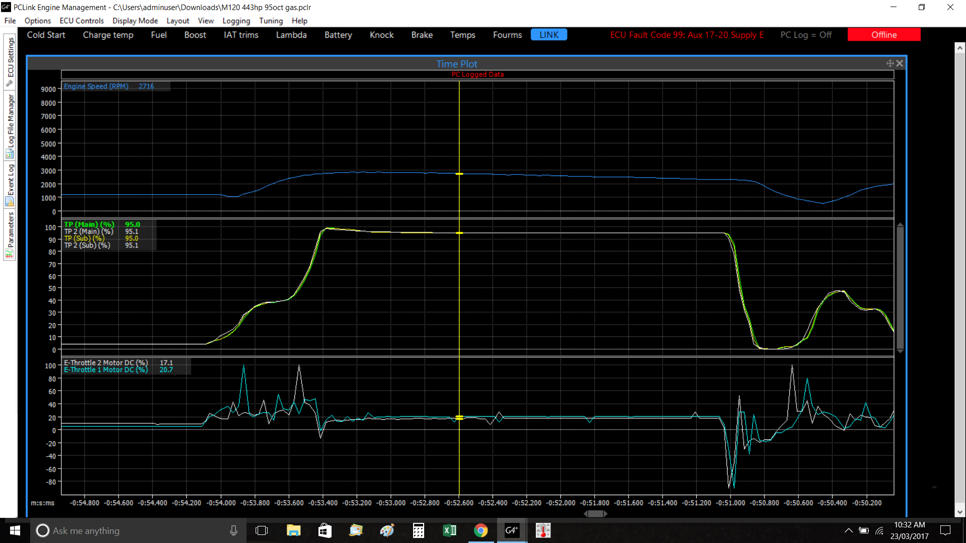
Added Pic and log
Hi Dave can you please have a look at the FP speed DC% during logging. Not sure if its normal but when you change the multiplier in the fuel pump control tab the FP speed DC% during logging does not match the duty cycle in the FP speed table. Im using a NZEFI hardware PWM fuel Controller and they are the settings with the instructions.
5 Bar turbosmart reg drop test 16 Volts.llg