


Ducie54
-
Posts
488 -
Joined
-
Last visited
-
Days Won
33
Content Type
Profiles
Forums
Events
Gallery
Blogs
Posts posted by Ducie54
-
-
I struggled to make it fit. There's 2x 3.5" magnaflow mufflers back there. In a dirty pulsar too
Here's a screen grab you may find interesting. Fuel temp into the rail is hotter than the fuel return. BOSCH temp sensor in and ethanol temp sensor on the return tho.

-
Here is some data i took when working out what PWM DC to run. You can see there is a point where the pressure drops considerably,

-
Do you have room for a fan on the cooler. He's a pic of my setup. It's only a small fan but works well.

-
-
I'm using the FP speed in open loop for the 1st pump and a 2D GP PWM table for the 2nd pump. Using injector DC% as the axis.
I haven't needed the 2nd pump just yet as Ive got 16volts to the pump.
What's the highest fuel temp you have seen?
-
Andy from adaptronic has a good video on FPR slope which you may find interesting.
I messed around with trying to reduce fuel flow all over the map and IMO not worth the hassle. I ended up just reducing the flow to 60%DC at idle and cruise to reduce pump noise.
Fuel temps still get above 40deg, only way I can reduce this further is to run a fuel pump like the Weldon's. Where the fuel does not run through the fuel pump motor.
-
Save the file onto the computer. Right click dwell table, import from file. Chose that saved file.
-
There's a reason why I said 15deg but meh. Put it on a tow truck as guessing will lead to more issues.
-
Did u follow my instructions or just load the map?
Are you just guessing the fuel numbers?
-
Your using a change over relay. Use a normally open dual 87.
-
Try this. Load this map.
Open the trigger calibrate widow. Click set base timing
Set ignition timing to 15 HIT ENTER, set delay to 40 HIT ENTER. Change offset until harmonic balancer reads 15deg HIT ENTER.
Leave window open and let water temp to come up, once at normal operating temp set idle screw so idle is just below target. Now hit done on base timing popup.
This map is using idle ignition table. Let me know how this goes.
Also any reason why your using MGP as a fuel Axis on a sr20ve? I would look and either MAP or TPS if you have poor map signal. Are you using a wideband to adjust the fuel table?
-
Are you currently running the latest firmware? Also make sure you press F4 to store to the ECU.
-
-
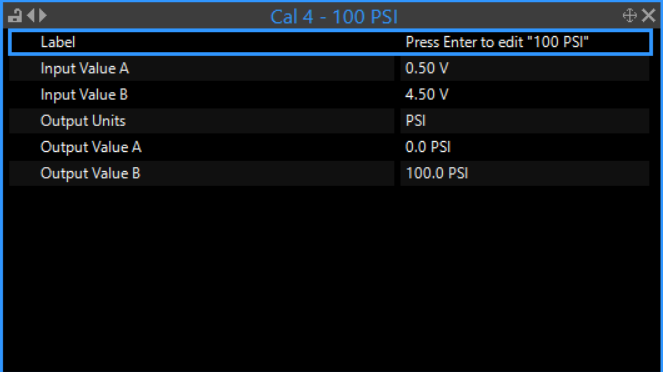
Use cal tables 4,5,6 for linear sensors. Your current settings are already linear and correct but it hard to visually see unless you do an interpolation over the top. Once you have your CTC setup you should also be able to Zero out the warm up enrichment table. I only use IAT correction as extra at idle and high Air temp

-
Also do you a pic and part number of the fuel pressure sensor? Calibration table looks different to the Honeywell sensors I use.
Also what map sensor are u using?
-
-
Unfortunately that tune is nasty in alot of ways. Idle ignition, knock and boost setup is not ideal either. BUT the fuel and ignition maps look pretty.
Was it a LINK dealer that did the installation and tune? Where abouts are you located?
-
I see just over 5 KPA pressure drop as an example. I find the pressure slope of the turbosmart 1200 to be very good, that's what I use.
I would try a better quality fuel pressure regulator and rewire the fuel pump using a realy close to the pump with large gauge wiring.
- Brad Burnett and krohelm
-
 2
2
-
-
-
Start by getting a nice flat boost cure @ 274Kpa then add axis above and below. Subtract DC% from 274 figure when boost is more and add DC % from 274Kpa when boost is less. 280 row is left at 0 as a safety, so if boost spikes it comes down quickly. Use the log file to help with DC figures.
High performance academy have some really helpful videos on this subject and many more.
-
-
I wouldn't be happy with the tunner if the ECU had to add or remove 40% fuel. Any more than 5% either way I would be looking into fixing the map.
-
I do that as the boost limit table has the axis as MAP.


Connect link with wideband
in G4+
Posted
Most are asleep this early in the morning.
Are you using the latest software/firmeware?