


Ducie54
-
Posts
488 -
Joined
-
Last visited
-
Days Won
33
Content Type
Profiles
Forums
Events
Gallery
Blogs
Posts posted by Ducie54
-
-
Yeah goods things take time Mapper, well worth it in the end. Just gives me time atm setting up ECU hold power and timers.
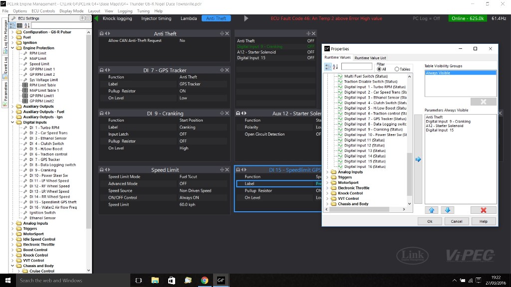
Another bug I thought that may be fixed when online is there is no option to label Aux outputs from 11 to 16. Also Digital inputs 11 to 16 do not show up labeled in run time values.
-
I cant even get axis setup correct for injector dead time table. Battery voltage is fine but can only get one row of diff fuel pressure, plus Short Pulse Adder Table entered numbers never show what i type. Also will not accept a negative number? ECU is online.
-
I'm using one one these in my water to air inter cooler system to monitor flow. Couldn't you use the frequency output in the GP limit 3D Table. Not sure how long it would last with straight methonal but in a water mix maybe alright.
http://www.seeedstudio.com/depot/Liquid-Flow-c-25_32/?ref=crumb
-
Howdy Dave
Good to hear things are getting better and back to help.
-
I need to splice about 8 wires off sensor grounds/+5v wires Is it OK to use the stock link harness wire or go up to 18g wire before I splice. Splice will be about 30cm back from the plug?
Thanks Nigel
-
I'm only new to tunning but won't the below work
Set the fuel equation to modelled- multi fuel than just change the axis of the multi fuel blend ratio to thermocouple 1. Initialize the axis so it does not interpolate under your EGT target switch temp.
Than as mapper said just use a GP limit with EGT as one of the axis
-
I'm running the Thunder and have alot of pressure and temp sensors. Is there a right or wrong way when grouping sensors?
I was looking at keeping all the high priority sensors together like TPS, MAP, IAT, ECT, fuel and oil pressure on the same sensor ground/+5 volt pins. Then using plug D for the other pressure and temp sensors.
Also when wiring in a external pull-up resistor for AnVolt temperature sensors I take it you need a resistor for each temp sensor and can not group them together. Like one pull-up resistor for two temp sensors.
Thanks
-
That's correct. Would save alot of headaches.
-
Where is the 12v feed to the coils taken from? It may have 12v with ignition on but none during cranking.
-
-
Curious to see the logs with different PID settings.
-
Both A and B both fit all though plug B is missing pin 14 which is ANV12 on the Thunder. I just used a spare pin from the C and D pin kits.
-
These look good. Can't wait to get my hands on one.
-
For those that are interested Ocean Controls in Australia sell dual channel voltage divides. Tested and adjusted mine on a constant battery voltage today and worked well. Still have to test which side of the SSR the signal needs to come from.
https://oceancontrols.com.au/search.php?mode=search&page=1&keep_https=yes
-
Thanks Guys
Dave im having a Dual voltage divider made, I can send it to you for testing if you would like.
Updated pic below

-
-
So like the below pic then?
If I wanted to read the voltage to the fuel pump would I need to use the GP input function of the AN volt channel?

-
Im looking at using a solid state relay to control fuel pumps and engine fans but not 100% sure on the best way to wire them. Googling shows there are several ways it can be done but you cant believe everything on the net.
Im using the Jaycar 100amp DC 4086 SSR http://www.jaycar.com.au/Electromechanical-Components/Relays-%26-Accessories/Solid-State/Solid-State-Relay-4-32VDC-Input,-30VDC-100A-Switching/p/SY4086
The SSR manual talks about using a diode to protect the relay against voltage spikes when turning off a inductive load, Another bit im unsure on.
Also is it possible to read the output voltage from the SSR to the fuel pump and have that inputted into the ECU?
-
Since link does not make the knock block anymore it would be nice to have a audio output plug on the ecu to listen for knock using headphones.
-
I'll send it your way tomorrow.
-
Cheers Simon. Can I get that done by Dave or do I have to send it to you.
-
Has there been any hardware or software updates since 2009 on the Display Link. I would like to get mine updated.
-
Thanks Dave.
Even if we could add attachments to the file. I've got bits everywhere. When I set up a PWM 3d chart the duty cycles don't mean much until you cross reference duty cycle to voltage then to water flow. Once you see my file you will understand. Having all that in one place would be nice.
Wiring is another situation, if you could attach wiring diagrams could save a tunner fault finding time. Plus it won't get lost.
Just ideas.
-
Simon could you please re attach the pic. I'm in the middle of trying to achieve this and a pic would help.
Thanks


Setup Analog to Can Converter
in G4+
Posted
I'm using this one over CAN.
http://www.turbofast.com.au/TFelectronics/PageFiles/CAN_EGT_Amp.html