


Anthony Parle
-
Posts
166 -
Joined
-
Last visited
-
Days Won
1
Content Type
Profiles
Forums
Events
Gallery
Blogs
Posts posted by Anthony Parle
-
-
Hi I want to kill the ignition when I am changing gears on my sequential. I have load cell on the gear stick and a rotary encoder on the box to tell me what gear I am in.
Could you please check that I have sent up the "Gear Lever Force", Gear Position" and Gear Shift Control" control correctly please as I am heading to the track tomorrow and want to make sure its right.
By the way I have the timing held back at 35 degree on deliberately.
Tony
-
Wideband O2
in G4+
Just setting up a G4+ Thunder and it came across as Lambda no longer wide band
Have we stopped expressing AF ratio in 14.7 and now moved the table to 0 to 5V?
Thanks
-
Hi I am wondering what is the maximum number of time per second I can log a input please?
Tony
-
Because I am programming using a engine dyno and a desktop computer of have plenty of screen realistate avaible is there any way I can keep the RunTime Value screen active all the time?
Thanks
-
Not sure I get were your coming from with the calcs
were did the 542 and 1015 come from?
-
The best would be if we had a bit of maths on the up and down shift.
If we assume we have loaded the rotary voltages into the "Gear Detection" section of "Chassis and Body"
Then on the up shift it would be
Current gear plus 1 --- End shift
On the down shift
Current gear minus 1 ---- End shift
The existing part of the program already has the current gear in a register in the program and it will instantly know when its in the new gear. In fact I would expect that the "Current Gear" had to be Stored to stop it being changed during the "gear Change action"
-
I am in support for more Virtual Aux,
I think more would enable more complex program of the ECU.
-
Hi Scott,
How many virtual outputs are possible?
It might sound silly but maybe we could configure one for each gear as regards the rotary position encoder on the box to make it closed loop.
-
Hi Scott,
Please accept my apologies up front if I am teaching you how to suck egg or have the totally wrong end of the stick,
If we do it the way you suggested it will execute the gear change even if for example the rev's are to high to change down. This is because the activation is brought about by input from either DI 1 or 2.
Right now I haven't got my head around it completely but it would be smarter to use the 3 conditions in a different way,
Say for up shift,
RPM > 1,500
Fuel Cut % >95%
Ignition Cut % > 95%
What you need to do is find 3 conditions that only occur during the gear change up.
The up just needs to be different to the down.
If would could Latch D1 & D2 then unlatch after Aux 1 or 2 had done there job that maybe even better as they will stay latched till the rest of the code in the Gear Shift Control starts its bit then away it goes.
Its also possible to set up say fuel cut to be within a tight range when you want the change to occur,
Fuel Cut % > 65 % and Fuel Cut % <= 67%
Maybe even have Aux 1 that allows up Shifts when the gear shift control is functioning and Aux 3 that does it direct input from D1 when its not. Not reason other then being tidy that you can't have two GP Outputs for up and 2 GP Outputs for down. Might need to use diodes to stop the outputs shorting.
As the saying goes "There is more then one way to skin a cat"
I think the gear change part of the PCLink is a lot better then I thought it would be. Its a great problem to nut out should be fun.
Keep well and thanks for the help.
Tony
-
Hi Scott,
How can I get a GP Output & Timers to changes based on the gearshift control.
If you could point me the were I could do that I could sort the rest.
Tony
-
Okay so I must be missing something in the setup of the Gear Shift Control or maybe not,
In the software it has the ability to lock out a gear change if the conditions are not correct, so for example if the rev's are to high then it prevents the gear changing down. The bit I don't get is why would that feature be in the software if it doesn't have the ability instigate the change. In other words if the driver pushes the lever forward with a sequential gearbox the box will change and the ECU has no ability to stop it.
The bit I may have missed but can't find, is the ability to output a digital event if conditions for the change are correct.
-
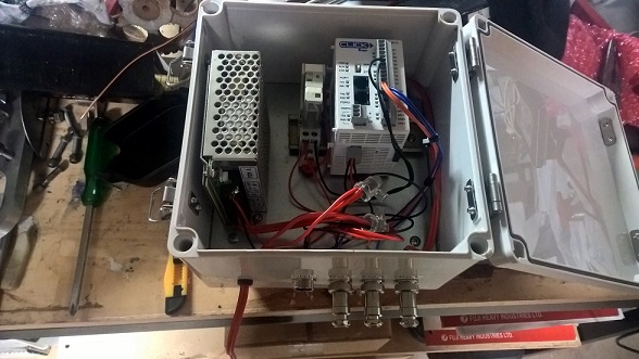
Hi Adrian,
I have spent about 5 minutes trying to think through this problem, be we maybe able to go in reverse, so instead of the LINK doing the brains work use a small PLC to fill the gape and have it tell the LINK what to do.
For my current sequential control unit I installed a small box with a PLC and it took input from the Strain gauge and the gearbox rotary position indicator. So its capable of ignoring Rev, Neutral and going up to 1'st. It works by killing the spark at the moment and getting feed back as to when its in the next gear. Pretty sure once we nutted out what the PLC would do and what the Link would do then we could replace the PLC with a small PIC. In the end it would just be a case if you wanted a Paddle Shift option with a Link then you buy the extra board. Just thinking for a second, if you are going to call the gear change then you don't need a strain gauge as its assumed when the change is done by the air cylinder.
Here is a photo of the PLC in the box.

-
Has anyone or is any one playing around with using the Thunder ECU to control a sequential gearbox but through a paddle shift.
I searched but didn't find much info.
I was thinking if need be could used a additional PIC board to add more ability to what the ECU can do.
-
Hi Scott,
Okay so to ask in a different way,
Does the stretching of the Cam belt throw out the timing of the ignition because we firer off the Cam sensor?
or is it that we fire off the crank sensor?
-
Couple of questions in relation to the general Link ECU methodology,
I have a engine with 12 tooth Crank sensor and 1 Cam, It has a timing belt. Does the Link ECU take TDC from the Cam Sensor every time or the Crank?
When we talk about a cycle we are talking 720 degree (Being 2 rotations of the crankshaft)?
If a injector has reached the limit of its duty cycle does it still open and close or does it just stay open?
Thank
-
Hi Scott,
I want to be able to hear the if a engine is knocking and its a flat 6 cylinder. If I order the following,
2 knock sensors,
Headphones
Knock Block
will all that come with the cables etc to make it work or do I need to order more bits?
Tony
-
Have brought a G4+ Thunder wanted to know is there any online manual to down load so I can sort the wiring out etc while it is in transport?
-
-
We have a running engine so its all sorted,
thank you Scott for the feed back, as a result tomorrow I will be purchasing a G4+ Thunder for the race car. This Link is staying on the engine dyno for R & D
-
Hi Grant,
I am based in Griffith NSW Australia, I have a Link G4 but was convinced by my tunner to buy Autronic SM4, which I have now sold unused so I could speclise on Link. Have a number of projects that need ECU's and want to stick with one brand.
Have Engine dyno I built for engine development.
Subaru SVX race car NA 3.3l chasing 400 hp,
Two Subaru F1 motors which are a flat 12 cylinder.
A Subaru open wheeler which we are building a fuel injected EA 81 engine with CI heads, it has a EA71 (1.6L) in it now.
As well as a couple of other projects down the track.

-
So I gave up with the standard Subaru cam and crank sensors so I replaced them Hal Effect units today, So now the timing light works on all the degrees and I have got the correct offset finally.
Issues,
I had to grind the lip off the cam pulley to give the sensor a clear read of lobe.
I am supplying the sensors with 8V from the ECU but Trig 2 must be draining to much current as the maximum voltage feeding back to the ECU is 1.8 V so I had to use the pull up resister in the ECU. May up the supply voltage to sensors to 12 V so as I can get a higher signal voltage.
-
Hi Rich,
Also forgot to mention that the car has a ppg sequential gearbox as well so I figured the Thunder would be better for that as well.
Thanks for the feed back its greatly appricated.
-
Hi I am looking at a new Link and see that the Extreme is the top of the line but the Thunder seems to have features that are more suited to me. Its for a car that races on track
I have a Subaru flat 6 cylinder and also want to go with individual throttle bodies.
Interested in some advise
-
Hi Scott
Checked Trigger 1 & 2 (status) when cranking both says, Yes,
Trig1 Error Count says 1


Sequential Gear control
in G4+
Posted
Thanks Adam for the feed back I will sort the issues out.
Tony