


Jurgen Biggelaar
-
Posts
416 -
Joined
-
Last visited
Never
Content Type
Profiles
Forums
Events
Gallery
Blogs
Posts posted by Jurgen Biggelaar
-
-
Hi Sebastian.
You first need to confirm the wires are going to the correct place on your pin out. Then to double check your settings in line with what the manual/help file says. If you attach a copy of the map I can see if there is anything obvious that may be not set correctly.
This is most likely how your set up should look on those DI's...
http://i903.photobucket.com/albums/ac236/linkelectro/camcontrol.jpg
Jurgen
-
Hi George.
It sounds like that very specific product is only useful when paired with a MoTEC. We have just released CAN for dash operation, however by looking at it, it may require special functions within the ECU for it to work... You would be best asking MoTEC if it works with our systems...
Jurgen
-
Hi Nathan.
This is another product that has recently been all sold, and not being replaced.
Jurgen
-
Hi Ryan.
The best thing you could 'try' is setting a spare AUX as a tacho, as this would work if the dash only needed a low level input. If this does not work, it's likely you have a tahco needing a high level signal in. This leaves you needing to have it modified (if it can be), or installing another that fits the vehicle.
Jurgen
-
Dan.
Thanks for the update. Yes we do find the DSE (Dick Smith) ones do work very well for most people.
Jurgen
-
Hi Simon.
Maybe reference to this post here with a link, and send it to [email protected]. Someone will take a look for you.
Jurgen
-
Good work Ben!
Jurgen
-
Any question there Matt?
I'll delete the thread if it was created by accident.
Cheers.
Jurgen
-
Hi Simon.
Try double checking the error values on your AN Volt channels. From 4.5.1 to 4.8.1 is a relitively large leap, so the likelyhood some internal memory locations have changed in that time means you may have some weird numbers in there.
If that happens on MAP or TEMP with 'cuts' in place... This could explain the non-running engine. Start with that anyway, but I will look forward to viewing that .pcl file. That will be the magic bit we need to see to give you some good advice.
Jurgen
-
Hi Markus.
I am a bit confused. The G2 has a 9 pin serial (D9) tuning port. Maybe you have a G1 with ribbon cable tuning port? You need the SerialLink for the G1, but a G2 only needs serial cable to connect to it. Can you confirm this for me, or can you give me some identifying numbers/letters from inside ECU?
Jurgen
-
Hi Scott.
Unfortunately it isn't just a pin out thing, there are electronics that need to be in this line.
I take it you mean USB to serial converter is what you have? And the final piece of the puzzle is between the serial plug of that, and the ribbon cable tuning port? If so, what you need is a Serial Link. This is a little black box available from Link, giving you what you need to complete your task (you will also need a serial extension cable to plug between the two).
Please email [email protected] for pricing and availability, and be sure to let us know where in the world you are as well. Just be aware, not all of the GTS Link units are PC Tuneable. You must have a sticker on the main microchip that resembles a 'Q' or above on the last charachter.
eg. GTS-Q or GTS-T is PC Tuneable.
Jurgen
-
Hi Fredde.
In the trigger wire cables you have red, black and 2 whites. The black wire is Trig1 (+ve side) with the white as the -ve, and the red is Trig2 (+ve side) and the white in there is the -ve side. Both of the negatives and the shield on the trigger wires are common, and terminate on the pin out as Sheild/Ground. These will by defalut also common with the block.
Do not connect the sheilding of the cables at the trigger sensor end, it is correct to have ground at the ECU end only, as it is wired on the loom. You have on the pinout you are looking at a 'sensor ground', this is the ground supplied by the Link for the negative to all your sensors such as, TPS, IAT and so on.
With your engine problem, it will help to know what it is... It maybe a very simple answer.
Jurgen
-
Hi Simon.
If you are OK to muck around in this stuff, the first thing I would do is check your triggering. It's harder to figure out what may have changed if we don't have the version it came from and to... Do you know what these were? If you are not sure about what to do in PCLink to rectify/check your issues, I would recommend taking it to your tuner as you will be playing with fire mucking with the wrong thing in there.
Jurgen
-
Hi Mike... Don't be sorry for the revival, keep it going! The HTC Desire is still crying for someone to come up with a cool solution
 The info you need is actually all in the PCLink help file as pasted below...
Bit field definitions...
Limits
Bit Position
Description
1
0
0 (LSB)
RPM Limit
Active
Not Active
1
MAP Limit
Active
Not Active
2
Speed Limit
Active
Not Active
3
Max Ignition
Active
Not Active
4
Not Used
-
-
5
Voltage Limit
Active
Not Active
6
Overrun Fuel Cut
Active
Not Active
7
Over Voltage Limit
Active
Not Active
8
Under Voltage Limit
Active
Not Active
9
Launch RPM Limit
Active
Not Active
10
WakeUp Status
Active
Not Active
11
AN Limit
Active
Not Active
12
Not Used
-
13
Not Used
-
14
Not Used
-
Bit 15 (MSB)
Not Used
-
Triggering
Bit Position
Description
1
0
0 (LSB)
Trig 1 Signal
Yes
No
1
Trig 2 Signal
Yes
No
2
ECCS Widest Slot
Yes
No
3
Not Used
-
4
Not Used
-
-
5
Not Used
-
-
6
Not Used
-
-
Bit 7 (MSB)
Not Used
-
-
Long Datastream Notes:
· 8Bit Data · 1 Stop Bit · No Parity · All words including the checksum are sent low byte first. · Checksum = 0xFFFF - (sum of all bytes) + 1 · Display Value = (Raw Data * Multiplier) + Offset Byte
Parameter Number
Parameter Length
Description
Units
Min
Max
Multiplier
Offset
Decimal Places
1 First
1
Byte
Sync Byte [$]
2
2
Byte
Data Length(inc start Byte and Chksum)
Bytes
3
3
Word
Engine Speed
RPM
0
20000
1
0
0
5
4
Word
MAP
kPa
0
500
1
0
0
7
5
Word
MGP
kPa
-100
400
1
-100
0
9
6
Word
Barometric Pressure
kPa
90
110
0.1
0
1
11
7
Word
Throttle Position
%
0
100
0.1
0
1
13
8
Word
Inj Duty Cycle
%
0
>100
0.1
0
1
15
9
Word
Inj Duty Cycle(Stg)
%
0
>100
0.1
0
1
17
10
Word
Inj PW
ms
0
50
0.001
0
3
19
11
Word
ECT
oC
-40
150
1
-50
0
21
12
Word
IAT
oC
-40
150
1
-50
0
23
13
Word
Battery Voltage
Volts
6
22
0.01
0
2
25
14
Word
MAF
g/s
0
350
0.01
0
2
27
15
Word
MAF
g/cyl
0
?
29
16
Byte
Gear Position
0
6
1
0
0
30
17
Byte
ECU Temp
oC
1
-50
0
31
18
Word
Inj Angle
oBTDC
0
719
1
0
0
33
19
Word
Ign Angle
oBTDC/oADTC(negative)
-100
100
0.1
-100
1
35
20
Word
CAM Inlet LH Posn
o
0
60
0.1
0
1
37
21
Word
CAM Inlet RH Posn
o
0
60
0.1
0
1
39
22
Word
CAM Exh LH Posn
o
0
-60
- 0.1
0
1
41
23
Word
CAM Exh RH Posn
o
0
-60
- 0.1
0
1
43
24
Byte
GP Temp - ANTemp1
oC
1
-50
0
44
25
Byte
GP Temp - ANTemp2
oC
1
-50
0
45
26
Byte
GP Temp - ANTemp3
oC
1
-50
0
46
27
Byte
GP Temp - ANTemp4
oC
1
-50
0
47
28
Word
AN Volt1
0.1
0
1
49
29
Word
AN Volt2
0.1
0
1
51
30
Word
AN Volt3
0.1
0
1
53
31
Word
AN Volt4
0.1
0
1
55
32
Word
AN Volt5
0.1
0
1
57
33
Word
AN Volt6
0.1
0
1
59
34
Word
AN Volt7
0.1
0
1
61
35
Word
AN Volt8
0.1
0
1
63
36
Word
AN Volt9
0.1
0
1
65
37
Word
AN Volt10
0.1
0
1
67
38
Word
AN Volt11
0.1
0
1
69
-
Hi Alan.
It's not really going to help you a lot because this is a narrow band input only. Don't bother with buying one to install if you don't have one already. They are expensive, and practically useless.
Jurgen
-
Hi Jay.
The photo is very unfocused and found it hard to make out. I think it says on the chip "D42EJAVO". If so, this is a generic wasted spark set up for Subaru EJ engines. This was done for AVO as some good base numbers to start with.
You could use this on any wasted EJ, but would still require a twiddle on the master fuel number and tuning of course. It will not work as it is, for ANY other make of vehicle other than a Subaru. This does not include Forrester, but some of those MAY even work with it.
It's base is a G1 LEM type unit, with a customised chip to make tuning a bit faster and easier for those that were doing a lot of these. It has 2 ignition, 2 fuel, and no anti-lag.
This is probably the closest manual that will work for you...
http://www.linkecu.com/support/documentation/g1-engine-management-documentation/lemv3manual
Jurgen
-
If this works for you Stevie... Just let us know by posting a response so others can make use of the posts. Thanks.
Jurgen
-
Hi Bevan.
You should have an 'On Level' setting on the DI there somewhere. If you have your 'On Level' set as 'High' for example... The ECU will know that the [device/switch] is meant to be in a physically ON state when it senses that line is high, and will display 'ON' in the F12 runtime.
The AUX/AC Pump F12 response. Weird. How is the relay wired? Let us know if the DI says the right thing after you adjust it.
Jurgen
-
Hi Rod
The outputs for the LC-1 are set for MAX V (+5V) at Max Oxy (Lean), and MIN V (0V) at Min Oxy (Rich)
Are you talking about your fault values set on the ANvolt channel? 0v & 5v? If this is the case, that rules out another potential for over fueling. So am I to assume you have it sorted by that last post? You are reading reasonable AFR (13-15 ish not tuned) and it's not smelling hella rich... Or are you still having issues?
Jurgen
-
^+1 Best explanation I have seen for ages Rod.
Actually there are 3 ways you can test... Rod's ways will all work, and there is nothing wrong with those, or the feature designed to test something for instances JUST like this
Option #3. Use the 'Test On' function on that auxillary (select 'test on' as the function and 'high' or 'low' side as an option. But there could also be another thing at play here. If this is a plug in G4, it is very possible it may not be able to high side drive anything that the OEM set up didn't usually.
What G4 unit do you have Robert.
Jurgen
-
Correct.
Lean = Bigger numbered AFR and inversly, Rich is a smaller number AFR.
I just noticed no one has mentioned the calibration, but you have also not replied with your WB make/model. Just check you have set the correct Voltage/AFR's on that ANvolt channel. This will most likely not fix the running of the engine because you can smell it's rich, but more if you actually WERE seeing 22AFR when it was rich is concerning.
Another thing to check will be the runtimes (F12, it's your best friend when there are probs), and in the 'Fuel' tab under 'Fuel trims' in there you will see anything that might be throwing in fuel because it thinks it needs it.
Sub note: If the WB cal IS way out and it IS callibrated incorrectly so you ARE seeing 22AFR even when rich, AND you have closed loop lambda turned on. It will be dumping hell loads of fuel in there!
Jurgen
-
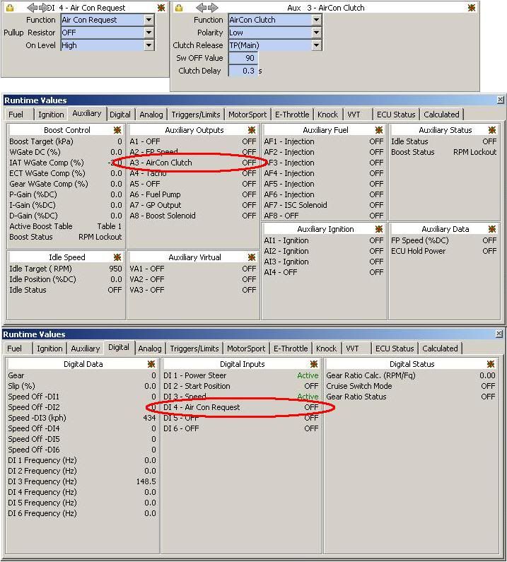
Hi Bevan.
This will most like be to do with the AUX or DI set up. This example pic shows a basic set up, but it is not nessisarily like your settings should be exactly. I would say just play with the DI's pull up resistor and on level, and the polarity on the AUX.
F12 brings up the runtimes (lower parts of the pic), and you can see the state of the DI or AUX there. Air con request, and air con clutch MUST exist in the same map as they tie in to each other, and there can't be one of them selected twice anywhere as this will cause probs.
Start with testing the DI by operating the button and looking to see if the runtime display shows a response. If not, change one thing... Try again etc.
http://i903.photobucket.com/albums/ac236/linkelectro/ACsetupexample.jpg
Jurgen
-
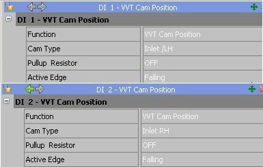
Hi Nigel.
The sync pulse usually appears between the last, and first in the firing order. When the ECU sees the sync, it will want to fire from #1 on the next firing event. Here is an example set up of how I think yours should look when done. Please keep in mind I am not aware of the sensor locations on your vehicle, so the multi-tooth posn. on trig1 & Sync mode on trig2 should resemble their actual physical location.
http://i903.photobucket.com/albums/ac236/linkelectro/examplemultimissing.jpg
Jurgen
-
Wicked... Good on ya Ian.

rb25 neo plug in
in Link G4
Posted
Hi Adam.
No. This NEO RB engine is purely an on/off solenoid, so it would be hooked up to an AUX with the function 'GP Output' (General Purpose Output). There you can set your switching conditions and for best results I think turn it on at around about 2000RPM, and off at about 5500RPM - 6000RPM. It does not require anything special as it is not variable cam control.
Jurgen