

T4700
-
Posts
71 -
Joined
-
Last visited
-
Days Won
2
Content Type
Profiles
Forums
Events
Gallery
Blogs
Posts posted by T4700
-
-
Second Load Axis issue.
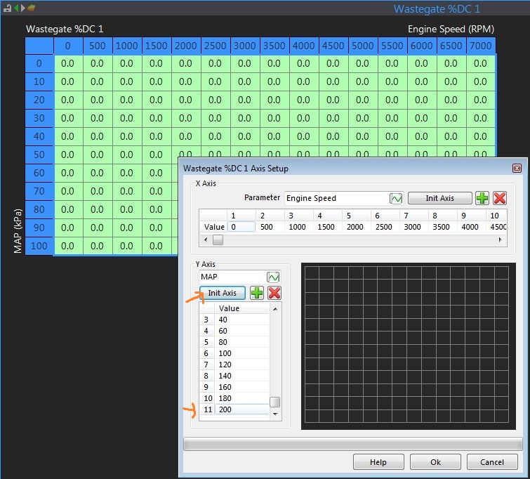
When I try to setup Load Axis for Waste Gate Duty Cycle
If I choose Axis Setup and klick on a value f.e. 100, the Popup window opens correctly to enter new value
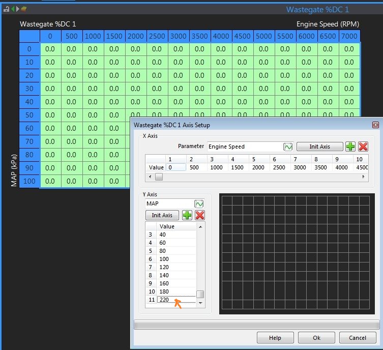
If I choose Init Axis, the Load Axis is genereted automatically up to 200. But when I click on the 200, no Popup window but the value changes direktly to 220.
If I click again on the 220, the value becomes 240.
If I klcik on the 240, the Popup window opens correctly to enter new value... dont understand that behaviour..
FIXED IN 3012


-
Hi,
I try to setup the load Axis (MPG) in my Link Thunder 5.5.6.29.26/1.9. Starting from -80, -60, -40, -20, 0 and than up to 300.
After I save the Axis, PCLink changes the values to -79, -59, -39, -19, 0...
When I change only the -79 back to - 80 and save again, Link PC changes the values to -79, -58, -38, -18, 0...
When I change only the -79 back to - 80 and save again, Link PC changes the values to -79, -57, -37, -17, 0...
Also when I just use init Axis in Axis setup. Axis Setup enters correct values -100, -80, -60, -40, -20, 0. But after saving it is -99, -79, -59, -39, -19, 0 :-/
Also when I just change the RPM Axis and leave the Load Axis alone. After saving, the negative part of the Load Axis is always decresed by -1 every time I save. So when I save enough times, they become zero automatically.
What is going on here??
best regards...
FIXED IN 3012


-
XXX
-
And now it is 100

-
Thanks,
my missunderstanding came from this sentence from the help:
"The following parameters are able to be logged in ECU logging mode:"
(thought I have to choose 25 from them)
So if I get you right, all these parameters above will be logged if I start ECU logging on V88?!
-
Hi,
I have a VIPEC V88 ECU in an Jetski.
I can not find any documentation about the settings for onboard logging for V88. I only found how to setup triggers for start/stop logging and how to download logs from the ecu.
But how can I setup the onboard logging parameters and how many parameters can be logged onboard?
best regards
-
-
Ok. I tryied that in PCLink. Nice
") thx
thxBut when I do this, I have no boost vs rpm map anymore and can not calibrate a boost curve
"Remember if you use closed loop boowt controll you span usually WG duty cycle table Target boost vs RPM. Fill the table too reach each boost target with the right WGDC. If you do that you can just put im your target map numbers in the target map and use the axis settings for things what you want. E.g. Egt vs rpm. "
-
target overlay map = AFR/Lambda Target Table2 ??
I nice additional feature would be a EGT Limit under Engine Protection.
Because if a richer lambda target table is not able to catch the EGT (maybe a failure in fuel delivery) a load limiter by EGT would be a solution
-
Of course there is a possibility to make that happen. Much much more is possible with the LINK platform, than what you may expect in the beginning. You can get very creativ with GP inputs, outputs,virtual aux, GP-limit table, and overlay tables. As an example use GP limit table to set an oil pressure minimum vs RPM or differential fuel pressure limit.
Use the target overlay table and span the axis EGT vs what ever you want. This way the target are changed and closed loop controll does follow the new target.
Usually i use target overlay to put some additional fuel in at high vehicle speed and use 4D ignition to take out some timing. Usually load and consequently combustion temperature are much higher and high road speeds.
woha... I will look at this in PC Link asap ;-)
-
@mapper - true post, I have nothing to add
Motronic knock control is supherb. Fortunately in Germany you can push a RS4 Turbo up to 300km/h on the autobahn. We do this gently uphill trough all gears to get maximum stress.
OLS Emulator does a good job because you can live tune via Laptop.These cars handle around 550-700 hp and there are a few with more than that. I had never one molten oem piston. (forged rods, bigger exh, bigger inj, bigger turbos etc etc)
Also exhaust temperature control does a brilliant job and is not only a safety feature. You can map two lambda targets and switch automatically to a richer target map at higher EGT. If the EGT is still rising, the EGT control kicks in. If the EGT still rising, load is cut. But when mapping, you have to secure that EGT control catches the EGT at around 970-980 deg C. I have seen chiptunes with 1015 deg EGT - thats to bad! Also many of them have issues with intercooler - IAT.
Unfortunately If one knows such nice features, he also wants to find them on the aftermarket ECUs
But If I learned right from reading. LINK Thunder has two EGT inputs and I can use them for EGT control via 4D fuelmap. Simply change one axis from load to EGT

The only issue I see is, there is no EGT dependant Lambda Target table. So If I use lambda control up to max rpm/load and EGT is richen the fuel, lambda control will turn it back to target

-
I think ignition timing is to complex to be done by a self tuning function in the ecu but what you mention is - so to speak - the sellf learning function to adapt a existing ignition map to different operating conditions.
OEM ECU recognize significant knock events and can learn to handle bad conditions like lower ROZ fuel f.e..
First you have knock control. If a knock event is recognized, ECU retards ignition by -X degree. If its still knocking another retard by -X degree. ECU gets the retard value from a map. Values are between -1,5 and -3,0 degree per knock event, dependant from rpm.
After that and no further knocking ECU is trying to advance ignition by Y degree, step by step, back to map value - learn value. How fast this all will happen is also read from map values. ECU learns the optimal retard value and stores this into permanent memory.
If engine is knocking violently and knock control is exceed, ECU cuts max permitted load. This is a extremly simplified explanation.
Keep in mind - OEM spends supremely money and effort for every engine in perfect working knock control.
But I see there is a non permanent memory in Link for knock retard values. Maybe if you analyze these values after a few runs (ECU must stay powered) you can use these values to refine your ignition map by hand.
But before you can use that, you have to do a reliable ignition map with headphones because you need a basemap that you know its not knocking. This is necessary to calibrate the knock control himself. Without that, ECU knows nothing about your engine behaviour.
This ist much more difficult than lambda ;-)
-
And I should add from a tuning perspective, knock control should be never used to compensate for a bad tune. The proper tuning of the ignition table should always be done with audio knock detection on a good load dyno.
Knock control is a proactive system, that are there to save the engine, if something goes wrong. It's no excuse to do the tune lazier.
And from mapping so many Motronic cars with OLS300 emulator yet I dont agree.Many Motronic cars hit the knock detection already with oem calibration.
The knock detection in modern ECUs is not only a safety feature. Knock control is to ensure the most efficient combustion. With knock control, modern engines have always a few knock events and if you switch knock control of there they wouldn'nt survive under normal condition. The engines can be mapped for best case (and not worst case) and the rest deg. of the knock limit will be detected by the knock control. But you also need a long term trim function for knock control so the ECU learns its limit. I agree with "you should not hit the knock control all the time" but there is no issue to hit the knock control under extreme conditions for a few degrees.
-
Ok, sounds like standard procedure but thanks for confirmation.
-
You just use the G28 (trig1) and G40 (trig2). Works like a charm
Are you using this in a high power S2 engine application ? (I am sure in Norway there are no S2 with oem power :-D )
Adjustable camgear and sprocket?
How do you ensure that the big hall window matches 100% to TDC of the crank? Strobe the flywheel and adjust the shift of the hall window on the camshaft?
thanks for reply :-)
-
Thanks for fast reply...
Ok I see, we have to go to 60-2 trigger wheel (no problem).
I dont like to have the hall window on the camshaft as TDC trigger.
thanks and best regards
-
Hello,
after getting a little deeper into the Link G4, I am glad to see that Link G4 seems to support the OEM 135 teeth Auditrigger.
I read the configuration of the auditrigger in Link help. I also squeezed the search function here about this.
Now I have a question.
The OEM Auditrigger ist working with two reluctor sensors for the engine speed/crankhome (G28 (135th) / G4 (1Pin)) and one hall sensor (G40) for the camshaft position.
I found the configuration for a 135th auditrigger in PCLink.
But in Link there is only a configuration for one of the two OEM Audi reluctant sensors. Seems to be the engine speed sensor (G28), which is reading the 135teeth.
But whats about the crank home relucant sensor G4? How is Link getting the right TDC of the crankshaft without crank home sensor? In OEM TDC (G4) and Hall window (G40) are also used to get the right ignition phase for full sequenzial ignition/injection and cylinder selective knock control.
Link has two Trigger inputs - one for crankshaft one for camshaft but OEM Audi needs 3 (2 for crankshaft)
How is that working in Link? Am I missing something?
best regards
.
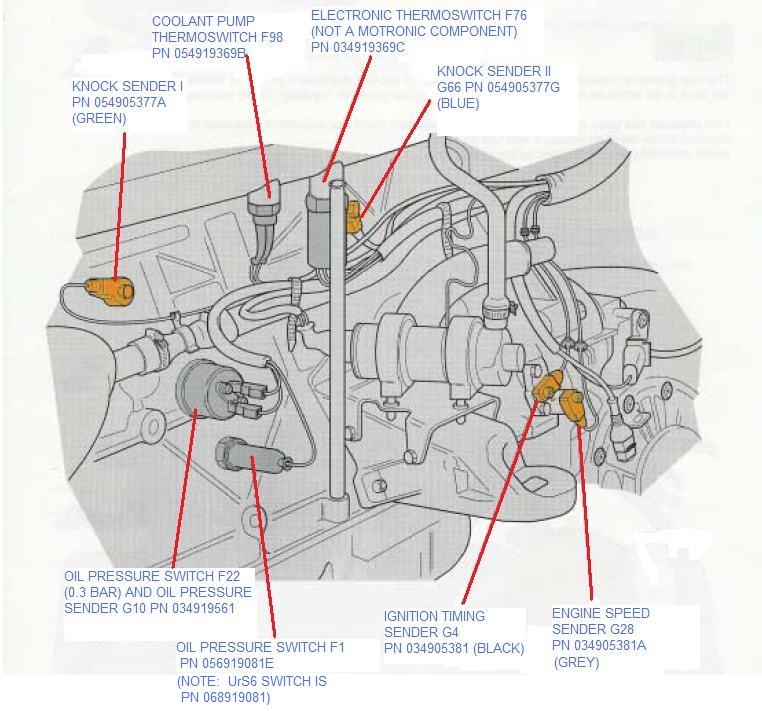
Hallgebersignal = G40
Zündzeitpunktsignal (TDC) = G4
Drehzahlsignal (rpm) = G28 -
thanks a lot... I will try this and report :-)
update
Ok seems like this is what I was looking for. Thanks. Now I have to play a little bit with the software...
-
Hi,
we are looking for a replacement for our VEMS ECUs.
As VEMS user "VEMS tune by statistics" is a very handy tool to analyze logfiles and refine the VE table and put that data direct to the config file.
I think Link provides a similar function with the mixture map?
I have the Link G4+ software on my laptop and want to get familar with the mixture map to get a better view of it.
Unfortunately the provided demo logfile has no lambda data so I can not use it for this testing.
Can anybody provide a logfile to me to play with the Link mixture map?
How are the Link calibration file and the logfile connected? How will I get the results of a analyzed logfile back to the calibration file?
In VEMS a logfile always contains the full config file data (aka calibration file), so after a run I can make changes direct in the logfile and save a config file from that. The logfile will not change from this. I alway get a new calibration file.
The logfile also shows me all changes I made to any calibration data during a run. So if I playback a logfile, I can see changes I made for any recorded time stamp. f.e. to VE table, ignition table, limiters etc.... So I can record one logfile, and test different settings in a run and in the logfile playback I can see all changes and effects in real timeline.
How is that implemented in LINK?
best regards
-
Hello,
is this 25 limitation only present when ECU logging or also when connected to Laptop (PC-logging?)
best regards


") thx
thx

Link Thunder Load Axis issue
in G4+
Posted · Edited by T4700
Thanks for fast reply") ...
...
yesterday I was wondering about some other things.
- > suddenly my MAP-Axis in Fuel Table1 was automaticaly cut.
I had a 22x20 Fuel table. I selected the Axis Setup
Allthough the Fuel table in the background had 20 MAP values - only the negative values where visible in the Axis Setup.
After leaving the Axis setup, the Fuel table was cut to these remaining negative MAP values on MAP-Axis.
I was not able to repeat this, so I dont know what happened.
COULD STILL NOT REPEAT
- > Link allows to use a 700kPa MAP sensor and we need this because of max. 550kPa boost pressure in one application.
But in Engine Protection, the max MAP value is only 500kPa
Also in Closed Loop Lambda Control the max value for MAP loockout is 500 - but we use (and we still want to use) Lambda Control under full throttle/full boost!
Maybe there are other tables that allow only 500kPa despite of using a 700KpA MAP sensor...
best regards
NOT FIXED IN 3012 - STILL PRESENT