


Nettlez
-
Posts
121 -
Joined
-
Last visited
Content Type
Profiles
Forums
Events
Gallery
Blogs
Posts posted by Nettlez
-
-
For the stock non vanos cam sync, what is the right setup for Trig-2 edge and sync mode??
thanks
sync mode I had got set it cam pulse 1x
-
Yeh will do this evening
-
Hi Nettlez,
Looking at the datasheet you linked to the calibration is the same as the one I linked to earlier. When you use the X-series calibration can you give some examples of what lambda reading you get for what voltage?
Scott.
Hi Scott,
It never move off of lambda 1.55 no matter what voltage is coming in, it's been from roughly 1.25v to 2.5v and it never moved off 1.55 lambda when using a the X series cal
-
Swapped my egt for cal 7 then put afr as cal 6 as its a lot easier that way :-)
-
So I realised I was being thick and that it was 1.55 lambda value being shown not 1.5v. So I measured the voltage coming into the ecu and what the gauge reads ties in with the voltage coming out to the ecu according to the tabe for my gauge. So therefore my problem must be with the calibration table. The gauge I have it AEM 30-5130, problem is im having trouble creating a cal table suit my gauge seeing as the x series one doesn't work with my gauge, it just constantly reads 1.55 lambda even though its receiving 1.2v which should be an AFR of 10.28:1 which should be a lambda of roughly 0.7. Even when I rev the car or lean the mixture off it still shows 1.55 lambda on the laptop while it changes on the gauge. I have used up all my linear tables for map sensor, ETG and boost control knob. How to I go about writing a table using tables 1-3 or 7-10? I can select volts vs lambda but then this gets confusing as the table in the AEM instructions is in AFR not lambda?
link below is to the gauge I have brought, map attached
-
He's got it running now with -84. His Ecu had the igniters built it FYI
-
Yer that seems to be the only things left. I will post with what AEM says when they reply
-
If you fudged the numbers in the calibration to match up with the gauge how do you know the gauge is reading right rather than the output numbers being right and the gauge being wrong? I have messaged AEM about it and so far they asked me to double check the analog negative is connected to ecu ground which it is. Wait and see what they come back with
-
Hi, as per the message I sent you
I'm afraid if you are using the m50 coils you will definitely need external ignitors. I went through all this my self a few months ago. If you look on the link below at the bottom it lists the ignitors as an extra, doesn't say there built in.
http://dealers.linkecu.com/E36Plus
You will need two of these
http://www.ebay.co.uk/itm/390972683826?_trksid=p2057872.m2749.l2649&ssPageName=STRK%3AMEBIDX%3AIT
and again two of these
http://www.ebay.co.uk/itm/111088132647?_trksid=p2057872.m2749.l2649&ssPageName=STRK%3AMEBIDX%3AIT
and to wire them like this
It would be a good idea to post a scope of your tirggers and what map you are using too. And as Adanw says ignition timing will need to be checked with a timing light, I brought this one and it worked a treat
http://www.ebay.co.uk/itm/110711496588?_trksid=p2057872.m2749.l2649&ssPageName=STRK%3AMEBIDX%3AIT
Hope this helps
-
You will need to wire some igniters in, standard Ecu has them built in, your effectively getting a weak spark. Your ignition timing should be -84 degrees providing your crank sensor wiring polarity is correct, if it's not then it will run on 276 but you will end up with trigger and rpm errors. Will put some links up to the igniters and plugs I used
-
It seems ok at the moment, it's just been to ticking over, not seen any big revs yet though. What problems do they experience? Trigger one error counter counting? Were they using both reluctor types?
-
So checked the log and no random high rpm figures, result :-) she ran lovely and stayed running, well chuffed. On with the next teething problems now, thanks for everyone's help
-
I have noticed something similar too. I have the analog version of the aem gauge and on the gauge its self shows an afr of 10.2:1 but the voltage coming in from the gauge to the Ecu is reading 1.55 which according to the aem cal chart should be 11:1 afr?
-
-87 seems to work well, it's running :-) yet to see if it's logging random rpm data log running. struggling to check it at zero which is the only mark I have atm as it goes to stall. I changed it at the female plug end of the loom, where the sensor plugs in
-
Yeh re synced using timing light, it was one degree out. Yeh done trigger cal and it doesn't fire, my figure is 276 so does that now make it minus 84?
-
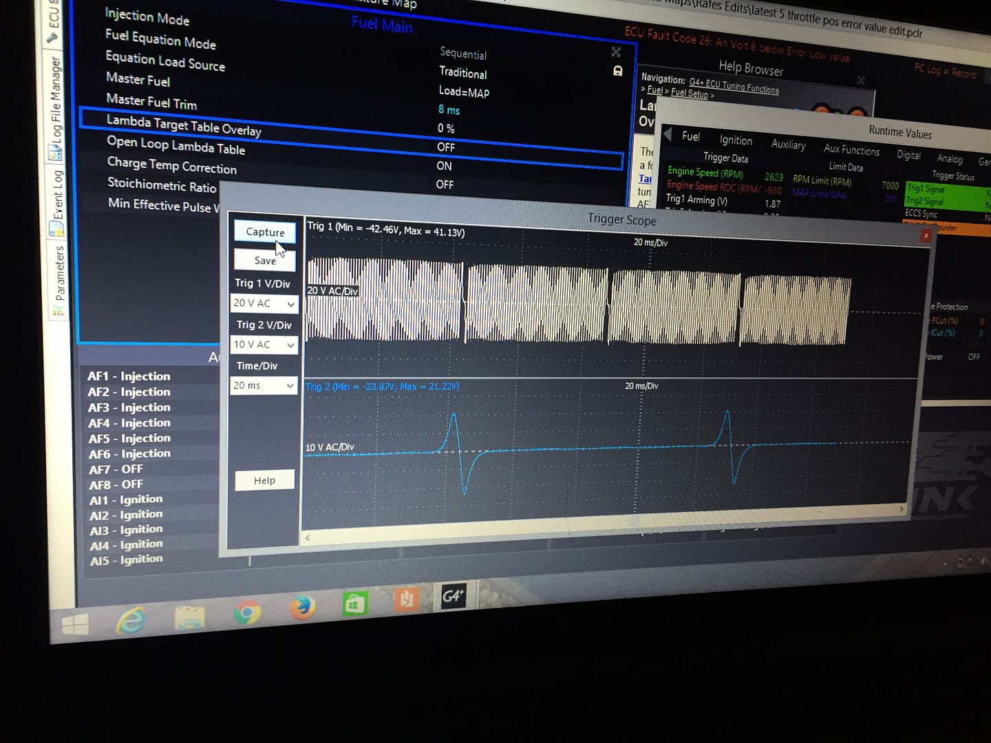
heres the new scope

-
So swapped the wires, trigger scope looks better, now it won't start :-( altered ignition angle, was out by 1 degree but no joy
-
Thanks, fingers crossed that sorts it. Will report back later
-
Ok will try swapping the wires when I get home later. Why would this cause random rpm signals?
-
Wouldn't let me upload the pic from my phone. Here's the link to a scope pic at 2500rpm
<a href="http://s1072.photobucket.com/user/Rafe_Nettles/media/Mobile Uploads/image_zps3yxxcw9s.jpeg.html" target="_blank"><img src="http://i1072.photobucket.com/albums/w378/Rafe_Nettles/Mobile Uploads/image_zps3yxxcw9s.jpeg" border="0" alt=" photo image_zps3yxxcw9s.jpeg"/></a>
Are you using the stock reluctor camshaft sensor? Set this to Hall effect and rising edge.. The camshaft sync is in the the missing tooth gap on these engines and the Link ECU is not happy with that. But set as Hall effect / rising edge works. (pullup off)
Yeh im using both stock sensors, this is the non vanos engine which uses both reluctor types, is the sync still in the missing tooth gap with the non vanos? I believe the vanos engines have a different crank trigger wheel? Thanks
-
-
you can also see it in this log when it was running a different map, rpm limit was 4500 upto 50 degrees ect. The only other thing I can link of is that the ecu was a wire in job and the last 20mm where it goes into the female plug is unscreened as the screen goes into the connector but surely there's no easy way round that?
-
yeh here it is
BMW E36 G4+ Xtreme Plugin rafe edit - open loop idle - rpm 10,000.pclr
I noticed it because under statistics it said my rpm limit had been reach 8 times, but the cars only been at no more than 2k(was set at 4500-7000 dependant on ect), I then changed the rpm limit to 10,000 and it went another two counts after running it again but the log doesn't show it going quite that high. When trying to go through it step by step under logging then value list it seems to keep skipping the data where it shows high rpm? The crank sensor is new but its a euro car parts job. Thinking I might end up going genuine bmw?
-
not sure if those log files will load, they wont on my laptop now. This one is though

new Aem x series wideband
in G4+
Posted
Done a short log scott, here it is
AEM Uego lambda not changing when set as AEM x series.llg