Rozsko
-
Posts
232 -
Joined
-
Last visited
Content Type
Profiles
Forums
Events
Gallery
Blogs
Everything posted by Rozsko
-
Correct. This has only avcs on the intake. And you are absolutely right. Removing the valve cover and checking those clearances will be the next step. The only question is when, as I need to go back to Italy now, so in an other couple of weeks. Thanks a lot to both of you for following up on my problem so many times. I really appreciate all your insights and hints!
-
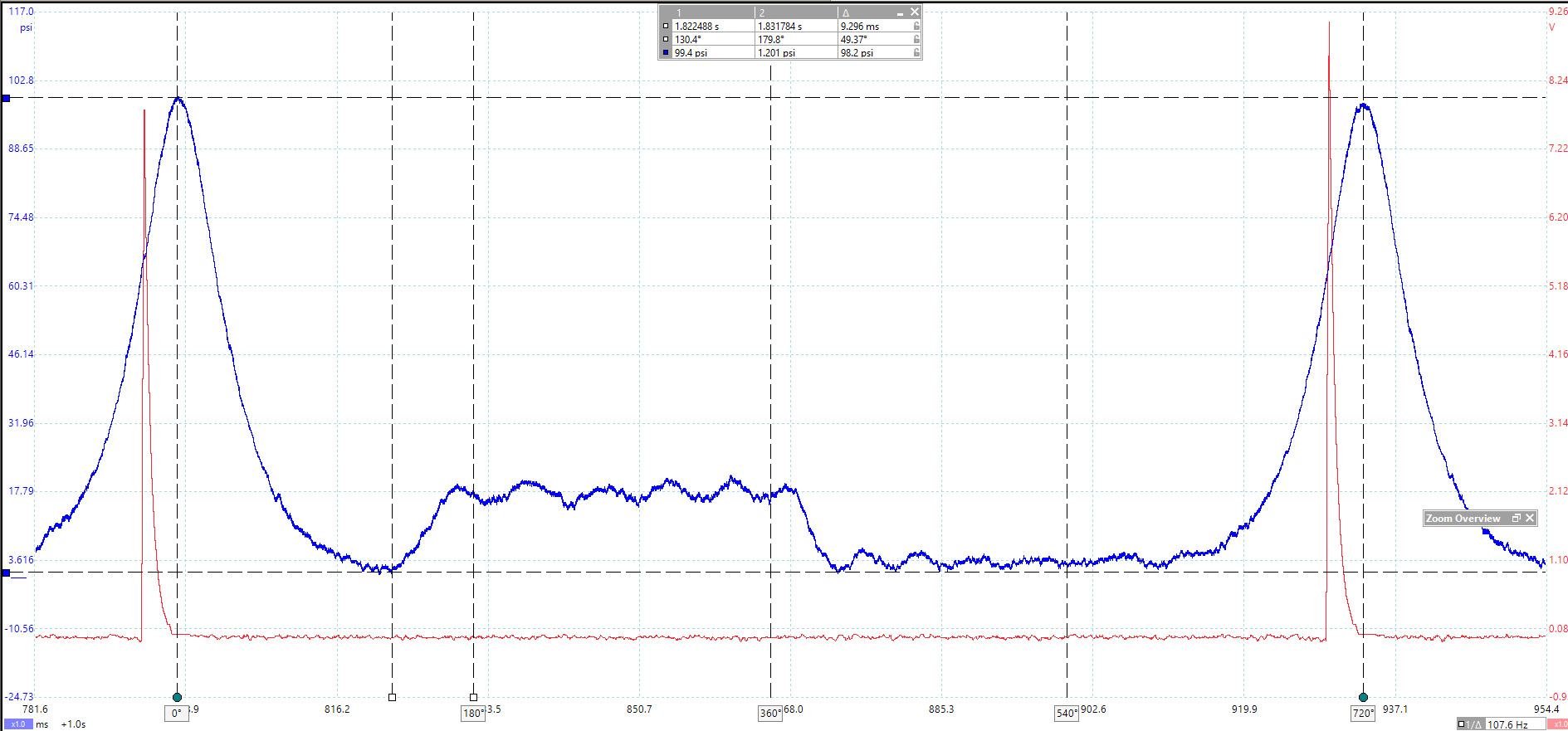
Took a little while as I took samples with multiple options, but here you go. Everything except cyl#3 pressure is cranking. As you can see, you were absolutely right, the measurement I took yesterday was not correct. It is interesting that the hashes and those bumps present on yesterday intake capture is gone on today's zoom3 capture. Cyl#3 running compression is ~50psi, cranking compression is ~117psi. Back pressure on snap test is ~35psi I did not really have the time and peace yet to think over what I can see on this picture, but on the WOT intake capture there is a major difference between two and two cylinders.

-
Well, I will repeat the test on cyl#3 then and see again. I am using a non-auto pico software, but I select the WPS in the probe setup, so that must not be a problem. LOL, that's exactly how it all started. I tried to scale the MAF sensor as I had an APS cold air intake that is bigger diameter then stock, but the AFR readings were jumping all over the place (+/- 1.5AFR). But I actually thought that is due to the misfire, as in that case only air is passing through the engine momentarily and that is obviously read by the wideband.
-
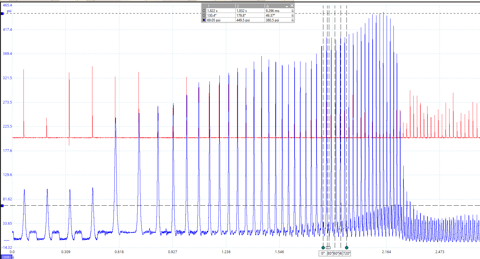
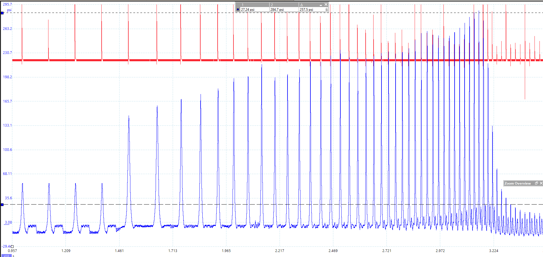
Ok, so I got home and spend some time with the car. (I will leave the interesting part last ) here is the cranking waveform from the crankcase through the dip stick tube, synced to cyl#4: Not sure if you can see anything on this, but I cant. I know it is noisy, but all vacuum pulls are roughly the same shape and size. Cranking intake waveform, again synced to #4 cyl: not sure if got the piston char lined up right, but even if I did, I can't get my head around the information shown. And finally #3 cylinder pressure waveform. Surprisingly, the compression is not low, but high compared to the other 3 cylinders, and the bottom does not go into vacuum. cranking: Idle: Snap: I think the backpressure here quite high compared to the other three (~65psi vs ~25psi), not to mention the peak pressure which is ~450psi in #3 and ~250psi in the other three. Now, on the backpressure: No cat, straight through 3.5" exhaust (with silencer though, so the neighbors don't scream on me) #4 snap throttle: The reason why #4 for comparison is because it shares the uppipe tube with #3.


-
it is not a known good waveform, but from the shop manual. So everything as far as engine assembly goes are brand new. Shortblock was ordered from IAG Performance, and since the block is converted to closed deck by them, I assume they skimmed it, but to be honest, I can't recall the specifics around that. Heads are also brand new. They are CNC ported Cosworth heads, so I don't think they were skimmed. Headgaskets are Cosworth 0.78mm.

-
So as I look at these diagrams more and more, I just realized, that the advance/retard that we see on the pressure waveforms is about 5degree.I think earlier did mention that the LH and RH cams dont exactly line up. Guess what, the difference is about 5 degree. The LH cam signal is advanced compared to the RH and it seems both the intake and exhaust cams are advanced on cyl#2. So it is not cyl#1 that is late as the RH CAM signal perfectly lines up with the crank.

-
No, these OE Subaru cams and are not adjustable. Exhaust is fixed, Intake is variable. I can, but what should be the ideal? I tried already with different settings like 100k, 200k, 500k, but did not really see any difference in the smoothness or detaildness of the curve. I am talking about the second TDC at 360 degree. if you see that ramp down from 0 psi to -10psi, that should be sort of straight or at least one smooth straightish (if that's a word ) curve. But if you look at it there is a little hump which I think is the IVO as if I measure the duration from that to the IVC event, it is roughly 226 degrees which is the total duration of the cam (although that is with the 1mm lift) as per the spec.
-
Thanks a lot Steve for the taking the time to take a look at this and reply. Those are great suggestions and I will certainly do those when I get back home in 2 weeks. They are 120 and 137 psi. Yeah, me too. And that was always in the plan to do, but unfortunately I had only a few hours to play before I had to leave. Also the thing that I did not mention yet but makes me more and more curious to check the other two cylinders is that cyl#3 is the nosiest cylinder of all 4. One more question in my mind regarding the late intake cam on cyl#1 is that how can that be if the right cam perfectly lines up with the crank signal and TDC indicated by the pressure peak perfectly lines up with the 5th spike of the crank signal which is TDC. So if everything is in sync, then how can it be late? the vacuum is -3.2psi on cyl#1 and -2.8psi on cyl#2 Yes, I follow your line of thought, but I would have thought that the compression is lower becasue of the late intake (opening - I think the little bump in the descending pressure after TDC is the IVO?) closing as in this case there will be less air trapped in the cylinder to compress.


-
Cyl#1 idle: Cyl#2 idle: So, the red and blue sections are mareked based on the Cosworth spec, measured at 1mm lift. Now to me it seems as if the exhaust would open roughly 9 degrees earlier then spec and the intake would close roughly 20 and 15 degrees earlier then spec. What I am not sure about if this could be due to the 1mm lift as obviously before the valves reach 1mm lift they already start flowing some volume as long as they leave their seat. Otherwise I can't see anything obvious on these charts. do you guys see anything suspicious?


-
Cylinder#2 cranking compression: Cylinder#1 cranking comression: The standard spec in the shop manual is 142-171 psi and the minimal limit is 128psi, this tells me that there is certainly something wrong, especially considering that I have 8.5CR Mahle pistons instead of the OEM 8.2. Although I am not sure if this is casued by some cam timing issue. As you can see, there is not much happening at the bottom of the chart, and this on its own is very strange to me. Idle compression graphs to follow. oh and btw, the WPS signal is 100 times nicer then the cheap ebay sensor's. I think where the 8bit scope suffers to show all the details is at the low pressure range where over time there is little change.


-
100us=0.1ms But other then that I fully agree. I bought a cheap one from eBay to see how it is going and it proves to be wrong. Now my worry is the scope itself, as I did not go with the Pico autodiagnostic one, but the generic only which is 8bit vertical resolution. The only problem is that I won't have the wps before I need to leave home next Monday. So it will be an other few weeks until I can get to the car again.
-
Little update, jut so that you have something to read. I contacted the USB Autoscope guys in Ukraine. The whole package is not too expensive (well, relative to the Pico stuff), but the only way they accept payment is through Western Union. Unfortunately they don't offer any buyer protection, like PayPal, so I was considering driving the car to Ukraine, as it is neighborhood country to Hungary. The headquarter is quite far, but they recommended some techs near the border who can do the diagnostic. This way I could avoid buying the kit and pay only for the diagnostic. So I was ready to roll, but then they figured out my car is far from stock and they backed out saying it would require a lot more time to diagnose as the standard process is for OE setups. Long story short, I ended up ordering a Pico WPS transducer, although pulling the engine and disassemble it would be cheaper, I just don't prefer that until I am really convinced it is necessary. Anyhow, I am not sure if the transducer will arrive next week, while I am home. If it will, then I will post up some more pics on the results, if not then couple of more weeks will need to pass, until I get my hands dirty again.
-
Ha ha! I love tst seminars. I already have payed for couple of their premium videos. This one will be a nice addition to the list. Thanks
-
I have an ignition lead going from the coil to the plug and have a Hantek capacitive clamp attached to it. Never thought to measure current on them, but I can try. I spend so much time on this yet, so a little more doesn't matter. I know. Unfortunately at the time the block was put together, I wasn't focusing on these things, as I have never thought it will go wrong. And because of that I did not record these numbers and was totally relying on the tech who put together the engine. Ok, so after the build, I had brand new DW850 incetors, and recently I changed to a set of ID1050X as they provide PnP calibration data for the Link ECUs. These are brand new too.
-
yea, I am trough those (and even more) and have purchased the ebook from him as well, but if you look at the waveform above, those are like white and black which leads me to think one of two things: 1) I am doing something insanely wrong when recording sec. ign signal, 2) there are some very bad things going on inside my engine's cylinders.
-
That is what I ordered for sure, but I will ask my wife at home to check the text on it. Good point and I can't wait to get home again mid oct to finally do a static compression test.
-
That's an awesome idea. I would never have thought about doing that. Plugs I tried both Denso and NGK, 1 range colder then OEM, but don't remember the code of those. Valve clearance (if you mean valve lash) was checked when we bolted on the the heads, but again can't remember. The tech who did the assembly said they are all good. Valve sealing were never checked, or at least I am not aware if were. Heads are Cosworth CNC ported, but were not coming as 1 assembled unit. Valves (oversized Supertech) were machined and fitted into the heads separately and the Cosworth cams were fitted after that. So different parteis were involved, yes. This week I had not much time to play with the pressure graphs, but next week I will take a deeper look at them. The other thing that bothers me is the shape of the secondary ignition wave form. They are nothing like the ones I would know to be good. oh, and thanks for the tip on that Windows app. Again, I would have never thought that you can find anything like that in the Windows app store.
-
Thanks Stevie for your reply again. First of all, how are you measuring the in cylinder pressure with an ECU? You wired it up just for the sake of it? Unfortunately I had no time to do the manual compression test before I went back to Italy (as I am working there at the moment and I go home only ever other month), but I found the scope trace saves on my laptop when I was doing the compression test on cyl#2 and 3,and as you can see the test shows an 11.5 % difference between the two banks. Again, I am not sure if the slow response of the 300psi sensor has an effect on the measurement or not. On the spark plugs, yes. I replaced those although the ones installed were brand new Denso plugs with 1 heat range colder. The 1 range colder thing aplies to the replacement plugs too. Regarding to the coils, I swapped them and also replaced one of them as I smoked that 4 times due to leaving the scope unplugged but connected to the spark plug connector. I have no idea about the valves. When the heads were put back together, we checked the lash and they were good, but whether they are seated correctly or not, I don't know. The valves are oversized, so there were some obvious machine work involved.

-
thanks a lot for reply. I already made a similar compression tester, but I did not trust it as the shape of the curve on the scope is too squary (if that is a word) as I assume the response time of the eBay sensor is too high. As far as 4 gas analyzer, I never tried that as I don't have one, but the misfire is pretty audible when it misses the beat.
-
Yes, that is something on my list of to-dos. That is just a freaking pain in the back, being a flat 4 engine. But is it likely that two cylinders on the same side having exactly the same compression issue due to internal mechanical problem? This is why I was investigating from a cam side as that would equally effect two cylinders at the same time. Anyhow, next week I will do the compression test.
-
Hey everyone, This will be a bit long, I am sorry about that, but I think knowing the history might help to understand the situation better. So, given a 07 EDM Hawk STi which I bought 4 years ago and had some serious coolant leaking problem with it. long story short, I ended up replacing the whole engine with an IAG closed deck block, forged internals, Cosworth heads with matching cams, Litchfield LM450 twinscroll turbo, ID 1050X injectors (had DW850 before that), etc... After the rebuild I was planning to tune the car myself but when I was trying to do MAF calibration (due to APS CAI being installed), the signal and the AFR readings were erratic, and Idle was sort of rough, so before moving on to the actual tune I wanted figure out if this is something wrong or just the nature of all the mods on the engine. Initially I did not realize but there were some misfire as well. Not enough to throw CEL, but definitely higher then normal (NO lightweight flywheel or crank sprocket). I bought a scope and started to look into sensor readings. While the signals were generally noisy from the ignition, everything seemed to be fine, no matter what I "fixed", no actual improvement was achieved. The only (I guess real) problem I found was the difference between left and right bank cranking compression test done with an amp clamp on the battery. There is about 15% difference in amperage and I would consider that not normal. I tried to do the a running compression test as well, but the transducer I built is far from superior, so that I was not able to use to diagnose anything. An other (real or believed) issue I found is a 5 crank degree misalignment of the left and right cam signal (this I suspected is due to timing belt jump, but that would be 15 degrees and I checked the markings and all wheel markings are lining up perfectly). Additionally I had something similar to the symptoms found in here: which is the signal of the LH cam sensor being inverting back and forth randomly at idle. Based on some technical reading this is usual with these hall sensors at low engine speed, but rotating the sensor with 180 degrees solved the issue for some and for me as well. Now that on it's own seems to effect the sensor calibration and I had the set the offset to 104 degrees instead of the OE value of 126. The cam solenoids seem to work fine, as I tested them by stepping through the vales from 0 to 40 degrees at around 1500RMP and the engine was almost stalling at 40 degrees and the cam sensor readings followed perfectly the commanded solenoid values. To be honest even today I am not sure if the square wave signals should both go from 5V to 0V, or one side should go 5 to 0 and the other from 0 to 5. Well that was little jump forward in time, as in the meanwhile I was able to source a secondhand WRXLINK107 and since then I am playing with that. The engine is running fine, I mean idles and runs well (without boost control), the AFR readings are more stable (much more) with the SD model, but I still have the misfire at idle and this along with the the left/right compression test difference and the cam signal misalignment still concerns me and I am really not sure if I could start the power tuning or should I do some more mechanical tests (which most probably would mean I need to pull the engine), but I threw too much money into the rebuild to scrap it during the tuning process (though I also bought a knockblock). Any hints, suggestions would be appreciated. Thanks, Béla current map + AFR target.pclr


-
Just a quick update. I was able to do the VVT test and I had to adjust both side with ~3degrees. The error count is 0 since then, but I still have the misfire. Thx
-
Ooops! that is a good point, just checked the base map and you are absolutely right. I forgot that I myself changed the Fuel equation mode to Modelled, as that was quite a while back before I had the ECU itself. Awesome! Thanks! Will try and see what is going on.
-
Just a quick update on the progress and thanks very much for the help so far. Yesterday I decided to try to start the car, but it did not work. It cranked and there was no errors really that I could spot. Today I tried again, but I realized that the AFR gauge does not show any values which means there is basically only oxygen in the exhaust, so I bumped up the VE table from ~20% to ~60% in the idle region and it fired up !!! I also had to adjust the idle stepper motor position % as after the initial warm-up period, the engine died. So for particular engine config the WRXLink107 base map is way off in the VE table and the idle control. (Unfortunately I do have some misfires which I had with the OE ECU too, and now I can see some VVT error counts on the LH side, so maybe that will be the culprit) Anyhow, it is up and running now, so time do some adjustments and tuning!
-
Yes, as the EDM STi don't have crusie control at all, so the steering wheel is lacking the buttons. Did not check all the related ECU connector pins, but as I checked B13 it is not pinned, so I guess the rest are not pinned either. I already did and both came back, but will try once again.